


Complete Guide to Cam Rollers: Needle Roller Bearings for Smooth Track Motion
Cam rollers, a specialized type of needle roller bearing, are integral components in applications requiring smooth and precise motion along a defined track. These versatile mechanical elements are widely used in industries ranging from automotive manufacturing to material handling, thanks to their ability to support high loads and maintain stability under dynamic conditions. This guide provides a comprehensive overview of cam rollers, including their construction, functionality, and key design characteristics. By understanding their operational principles and the various types available, readers can gain valuable insights into selecting the right cam roller for specific applications, ensuring optimal performance and durability in demanding operating environments.
What are cam rollers and how do they work?
Definition and basic components of cam rollers
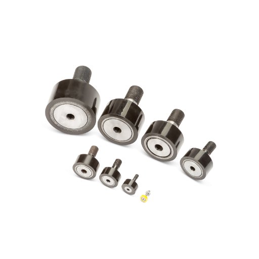
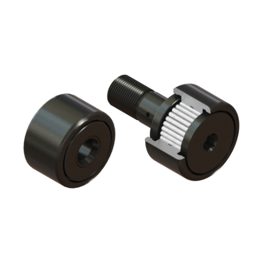
Cam rollers are specifically crafted rolling elements used in linear motions with the ability to bear maximum loads. They comprise a cylindrical outer ring which works as the rolling surface while the inner ring is supported by ball bearings or needle bearings allowing smooth motion. The outer ring can either be crowned or flat depending on the application. The most commonly used cam rollers are those having an external crown. This is because it reduces edge stresses during operation. Other key elements include othe uter ring, bearing assembly, and mounting features with the shaft such as a stud or a through hole.
- Load Capacity: Ensures durability when the cam roller is subjected to operational stress.
- Material Composition: Hardened steel is commonly used for cam rollers to increase wear resistance. However, polymers can be used in specific engineered environments.
- Temperature Range: Standard design limits the temperature between -20°C to 150°C.
- Lubrication Type: Common systems are oil and grease. Altering this can affect performance and maintenance intervals.
These definitions are what help deduce what tolerances the cam rollers need to follow. From there, it aids in the selection of achieving the highest performance while decreasing the degradation of the mechanical system.
Cam roller mechanism and interaction with tracks
In track-guided systems, where durability and precision are paramount, the cam roller mechanism is a crucial subsystem. These rollers are designed to operate in tracks that enable linear or rotational movement, subject to a variety of loads.
- Material Composition: The most common material used for rollers and tracks is high-quality steel due to its unparalleled hardness. However, other low-loading and corrosive environments may require materials such as polymer composites.
- Load Rating: It is essential to comprehend the dynamic (cyclic) and static load rating of the rollers to guarantee against deformation and damage. If the focus is on high-load systems, it may be wise to use oversized rollers or add additional supports.
- Surface Hardness: To reduce wear in tracks and rollers during heavy-duty operations, surface hardening is recommended. Ranging between 58 and 64 HRC is considered appropriate.
- Lubrication: Since friction and the lifespan of the roller greatly depend on operational speed, temperature, and environmental cleanliness, oil or grease lubrication should be selected carefully.
- Clearance and Alignment: It is necessary to ensure proper alignment of the track and cam roller to minimize wear and noise, and enhance system efficiency.
By evaluating these factors systematically, I can align the selection of materials and configurations with the application’s requirements. This approach guarantees mechanical efficiency, reliability, and a longer operational lifespan.
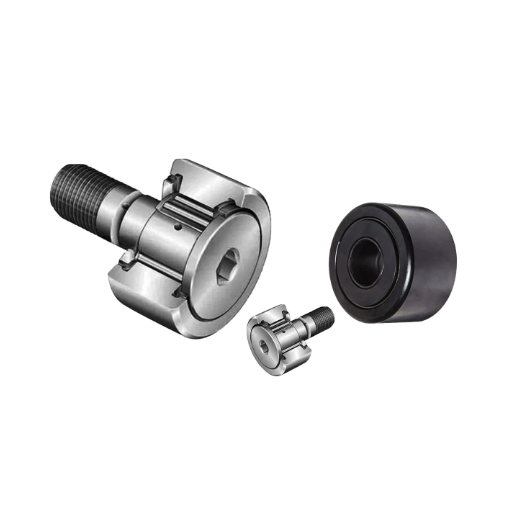
Types of cam rollers: stud type vs. yoke type
When considering stud-type cam rollers versus yoke-type cam rollers, I analyze their respective characteristics to align with the application’s operation.
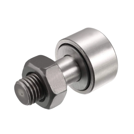
- Stud Type Cam Rollers: They consist of a cam roller that incorporates a base cylinder to facilitate connection. Reduction of assembly components such as fixing parts makes it easier to integrate into smaller-sized systems. Along with those advantages, stud-type cam rollers are also easy to install and usable for moderate levels of working loads. Their mounting plate stud diameter, thread size, and the outer diameter of the roller range from approximately 10mm to 100mm.
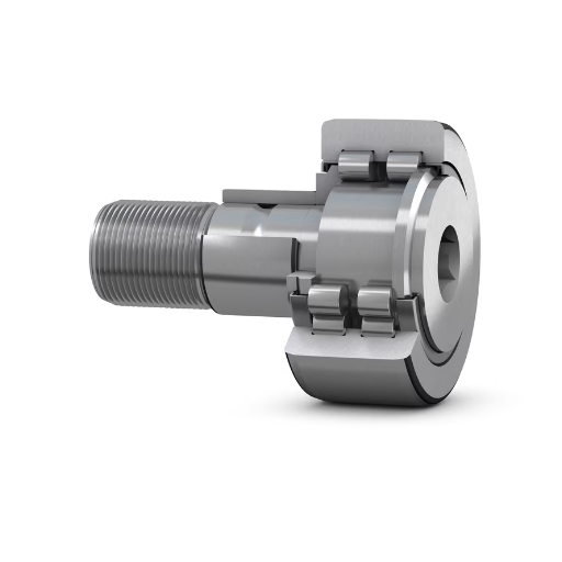
- Yoke Type Cam Rollers: As distinct from the stud type, yoke-type cam rollers are mounted on separate supporting shafts or axles. This allows for a greater working load to be placed on the yoke-type cam rollers and better load distribution which makes them ideal for heavy-duty use or high radial load working conditions. They also have a wider range of bore diameters e.g., from 10mm to 60mm, along with larger outer diameters than the stud types e.g., up to 200mm or more in industrial use.
When I analyze these two types, I select the one which is the most convenient about the available installation surface, the weight that the unit will have to bear, and the upkeep that will be required. For situations that are particularly high in load and robustness is critical, yoke-type rollers are generally preferred. On the other hand, stud-type rollers are better for easier assembly and lessened weight. This approach makes sure that the mechanical design is acceptable in both operational and engineering aspects.
What are the key features and benefits of using cam rollers?
High load capacity and reduced friction
For one of the robotic components involved in the assembly process, cam rollers have been selected `for their ability to support simultaneous loads while keeping friction contact to a minimum. In their construction, hardened steel combined with precision machined components ensures reliable operation under high loads.
- Load Rating (Dynamic) 30000 N: Specified for up to 30,000 N, this assures dependability under significant cyclical forces.
- Load Rating (Static) 50000 N: permits an explicit limit of 50000 N which is more than enough for static or dormant cam rail arrangements.
- Coefficient of Friction: energy efficiency gained through reduced movement resistance. The rolling elements offer 0.001 to 0.002.
- Temperature Range: able to operate within a range of -20 to -120 without a loss of function.
Regarding the conveyor and other equipment, these are the technical characteristics that allow cam rollers. It makes them gainful in harsher environments withstanding high levels of wear, excellent tolerances, and efficient operation.
Compact design and space-saving properties
The restrained proportions of cam rollers enable them to be easily integrated into small areas of a complex system where space saving is important. Each of them is designed to give maximum load-bearing capacity at their minimal dimensions. This is useful for areas that have stringent space requirements. Their well-designed shapes assist in correct positioning and installation, therefore reducing the amount of extra mounting hardware needed. A good example of this is how cam rollers are often used in small automation systems and even in the assemblies of conveyors.
- Outer Diameter: Approximately 16 mm to 150 mm. It depends on the application requirements.
- Load Capacity: Radial and axial loads from 500 N to 50,000 N are supported and assure durability and functioning.
- Mounting Clearance: In most cases, the installation requires 5 mm space which makes it helpful in less spacious mechanisms.
These characteristics are sufficient to justify the application in cases, where performance and precise configuration are needed with limited spacing available.
Versatility in various applications and industries
Our solution demonstrates exceptional versatility, making it suitable for a broad range of industries and applications. From automotive systems and industrial machinery to aerospace technology and medical devices, the adaptability is credited to the robust technical requirements it offers:
- Load Capacity: Ranging from 500 N to 50,000 N for radial and axial loads, the received load capacity is very reliable in most operational conditions.
- Compact Design: In systems with tight spatial limitations, only 5 mm of isometric clearance is permissible for mounting which improves the performance of small-scale mechanisms.
- Durability and Precision: Timescales focused on design longevity emphasize an increase in performance, which is a crucial requirement of high-precision motion control applications.
The performance, spatial, and reliability standards are met, while also offering practical functionality for the wide range of engineering problems, such as space suffers. This enables the maintenance of the edge in every field of engineering innovation.
How to choose the right cam roller for your application?
Metric vs. inch sizing options
The choice between the metric and inch sizing systems for cam rollers heavily depends on the particular technical and operational needs of your application. International applications require the use of metric sizes which are usually compatible with globally sourced components due to their adherence to ISO standards. Systems designed around imperial measurements like those found in the U.S. are better suited to the inch sizes.
- Dimensional Fit and Compatibility: To facilitate efficient assembly and operation, discrepancies between the selected sizing standard and the existing components of the system should be eliminated.
- Load Capacity: Operational demands should be met with load ratings expressed in Newtons or pounds. The reliability of the system and bearing life depend directly on load ratings.
- Precision and Tolerances: Tight tolerances in line with ISO grade classifications are common with metric components, but parts based on inches should be evaluated using ANSI/ABMA standards.
- Environmental Conditions: Between sizing systems, the availability of materials and coatings may differ, impacting mid-range corrosion resistance and heat tolerance.
With a deep understanding of these factors in the context of the application requirements, maximum performance while ensuring the system is reliable and compatible can be achieved.
Selecting between crowned and cylindrical outer rings
When selecting between crowned and cylindrical outer rings, I focus on the specific application requirements to determine the most suitable option. Crowned outer rings are ideal for applications involving misalignment or deflection, as their curved profiles allow for better stress distribution and minimize edge loading. On the other hand, cylindrical outer rings provide higher load-carrying capacity and are more suited for applications with high radial loads and precise alignment needs.
- Misalignment Tolerance: Angular misalignments are tolerated by crowned rings with a range of 2-3°. On the contrary, stress-concentration-sensitive applications with cylindrical rings need to be precisely aligned.
- Load Distribution: Stress concentrations along the raceway are reduced as crowned rings shift the most loadable dynamic position from the middle to the edge of the raceway. For cylindrical rings, the total load must be ideally distributed to not lead to deviation from the raceway to gain severe uniform load distribution.
- Radial Load Capacity: Due to the geometry of the crowned rings, they almost always have lower radial load capacities than cylindrical rings owing to the decrease in contact area.
With consideration to operational conditions, I am sure the outer ring design I selected works correctly in the load envelope boundaries I established.
What are the common materials used in cam roller construction?
Bearing steel and high-carbon steel options
In selecting materials for the construction of cam rollers, I focus on two main possibilities about their mechanical characteristics and the application at hand:
- Bearing Steel: For most of the applications, I employ chromium-alloy bearings steel, such as 52100 (ASTM A295), that has a significant degree of hardness (60-67 HRC) along with excellent erosion and fatigue strength. Bearings steel’s structure can be made uniform during the manufacturing process by using homogenous microstructure heat treatment. This property, coupled with superlative cycles of repeated stress, helps in achieving great performance efficiency.
- High Carbon Steels: For easier applications with moderate load and speed, I use high carbon steels such as 1045 or 1095. These types of materials have sufficient hardness (up to 55 HRC after heat treatment) and adequate toughness. Less demanding uses, such as these, are practical and economical due to their lower costs and ease of machining. However, high-carbon steels are not recommended for continuous severe high-stress applications due to their disadvantageous wear and fatigue properties.
By carefully selecting the material, bearing in mind the load, speed, and other environmental factors, I’m certain the cam roller achieves a balance between optimal performance and cost-effectiveness.
Stainless steel cam rollers for corrosion resistance
In situations where corrosion resistance is important, I usually use cam rollers made with 440C or 316 stainless steel. These steels provide a great deal of protection in corrosive conditions due to their high chrome content which forms a passive layer that protects against oxidation and rust.
- 440C Stainless Steel: This martensitic grade is capable of attaining hardness greater than 60 HRC after heat treatment and offers good strength and wear resistance. This grade is appropriate for moderate corrosion conditions such as food processing and semi-outdoor conditions.
- 316 Stainless Steel: This austenitic grade has increased amounts of molybdenum which increases corrosion resistance to chloride-pitting and other types of corrosion. It has lower hardness and is suited for more aggressive conditions like marine and industrial chemical processing.
I ensure that the engineering material is compliant with the application requirements by selecting the material while looking at the operational environment such as moisture, chemicals, and ambient temperature. Preparing for corrosive conditions is one of the performance aspects that both options manage to achieve and remain cost-effective and durable for different use cases.
Chrome-plated surfaces for improved durability
Chrome plating is mainly done to improve the surface roughness of materials due to its exceptional strength and resistance to wear. This electroplating method modifies the surface of a substrate material by adding a thin layer of chromium which improves the substrate’s physical properties.
- Hardness: The plating of chrome utilizes a surface hardness of 850 to 1000 HV, which highly increases the lifespan of components or materials that are subjected to abrasive and mechanical wear.
- Corrosion Resistance: Even if chrome-plated surfaces are not as protective and corrosion-resistant as stainless steel, they have moderate protection against varying environmental aspects, especially indoors, and with limited chemical exposure.
- Coefficient of Friction: The process reduces the coefficient of friction, therefore, ensuring smooth surface interactions that require low friction. Some examples of such applications include hydraulic cylinders and mechanical sliding parts.
- Thickness: Standard plating thickness varies from 50 to 500 microns, which is from 0.002 to 0.020 inches, depending on the functional and wear requirements of the application.
- Adherence to Base Material: Proper pre-treatment helps achieve a robust attachment of the chromium layer to steel, copper alloys, or aluminum materials.
When selecting chrome plating for a project, the operating conditions and performance criteria should thoroughly justify these factors. Its application is ideal for environments requiring enhanced abrasion resistance and improved aesthetic appeal without exposure to extreme chemical or thermal stresses.
How to properly install and maintain cam rollers?
Installation techniques for stud and yoke-type cam rollers
Precise adjustments must be made when installing stud and yoke-type cam rollers to ensure they perform optimally and have a long lifespan.
- Stud-Type Cam Rollers: The stud-type cam roller is fixed by inserting the stud into the prepared housing or support structure. Recommended torque values should always be used according to the thread type and housing material to avoid loosening or over-tightening. For example, a tightening torque of about 49 Nm (Newton meters) tends to be appropriate for an M10 thread size. Always verify alignment during installation so that the cam roller is free to move over the desired path.
- Yoke-Type Cam Rollers: Yoke-type cam roller is inserted in a mounting shaft or pin. The shaft diameter must match the yoke bore so that it fits properly as specified in the product manual (for instance, a yoke bore of 30 mm should be matched with a shaft of 30 mm). Ensure proper lubrication between the moving parts to avoid excessive friction while working. Employ shims or spacers if needed to adjust the roller’s position relative to the track or guide.
When using either type, it’s critical to make sure that the bordering parts allow enough distance to avoid misalignment or over-lateral force. Adequate lubrication is highly important; grease or oil intended for the appropriate load and speed should be used. For instance, grease NLGI grade 2 is good for general use, but specialized lubricating elements may be necessary for high loads. Performance stability and service life can be achieved with regular maintenance procedures like wear examination, relubrication plans, and keeping contaminants out of the rolling surfaces.
Lubrication requirements and best practices
- Choosing the Right Lubricant: Choose the correct lubricants specifically designed for the task. When lubricating devices in NLGI Grade 2 general-purpose situations, a grease-rated NLGI Grade 2 suffices. Heavy-loaded devices or those exposed to high temperatures will require lubricants with extreme pressure (EP) additives or synthetic base oil. You also need to check the viscosity index (VI) of the lubricant to ensure that it matches the operational speed and temperature requirements. For example, a kinematic viscosity of roughly 100 cSt at 40 degrees Celsius is ideal for medium-speed equipment.
- Lubricating Routine: Based on set relubrication intervals and load intensity in operational hours, create a relubrication plan. For instance, components used regularly may need greasing after every 500 hours whereas those used in extreme conditions may require attention as soon as they hit the 100-200 hours mark. Do not forget to always check the equipment manual for comparison with particular guidelines.
- Control Environment: Contamination is one of the primary reasons that lead to lubrication failure. Make sure seals and barriers are functional guarding against dust, air moisture, or any debris that may block the lubricating oil. Grease guns, bearing,s and lubrication discipline together with clean storage of these tools will help avoid the contamination of the system.
- Application Techniques: The lubrication should be applied with precision on the contact surfaces. This may be done by using grease guns or oilers. Both over and under-lubrication can be detrimental: over-lubrication can increase the temperature of the parts while under-lubrication can increase wear. Always follow the guidelines set in the technical manual.
If these technical requirements are followed as some suggestions, the reliability of the maintenance systems will be achieved, putting to minimal the wear of the machine components and increasing their service life.
Frequently Asked Questions (FAQs)
Q: What is a cam follower and how does it function in track motion systems?
A: A cam follower is a type of needle roller bearing designed to follow the contour of a cam or track. It functions by providing smooth, low-friction motion along a predetermined path, reducing wear, and ensuring precise movement in various mechanical applications.
Q: What are the main components of a cam roller?
A: The main components of a cam roller typically include a thick-walled outer ring, needle rollers, a cage to separate the rollers, and often a stud head or flange for attachment. Some designs may feature a full complement of rollers without a cage for increased load capacity.
Q: How do I choose the right cam follower for my application?
A: When selecting a cam follower, consider factors such as load capacity, speed, environmental conditions, and space constraints. Choose from various sizes and designs, including solid rollers, eccentric options, and flanged varieties.
Q: What are the benefits of using cam rollers in track motion systems?
A: Cam rollers provide several benefits in track motion systems, including reduced friction, smooth operation, extended service life, and the ability to handle high loads. They also help distribute forces evenly, minimizing edge stresses that may occur in the track.
Q: How do I properly maintain cam rollers to ensure optimal performance?
A: To maintain cam rollers, regularly inspect for wear, ensure proper lubrication, keep the track clean, and replace rollers when necessary. Follow the manufacturer’s guidelines for maintenance intervals and lubrication types. Proper care can significantly extend the life of your cam rollers and track system.
Q: Can cam rollers be used in high-speed applications?
A: Yes, cam rollers can be used in high-speed applications. However, it’s crucial to select the right type of roller for your specific speed requirements. Some cam followers are designed with special cages or lubrication systems to handle high-speed operations more effectively.
Q: Where can I shop for cam rollers and related products?
A: You can shop for cam rollers and related products from various suppliers and manufacturers. Many industrial supply companies offer a wide selection of brands and types. Online marketplaces and specialty bearing shops also provide options to purchase cam rollers in different quantities and specifications.
Q: How do I determine the correct quantity of cam rollers needed for my project?
A: The quantity of cam rollers needed depends on your specific application, track length, load requirements, and desired performance. Consult with a bearing specialist or the manufacturer’s engineering team to determine the optimal number and spacing of cam rollers for your project.
Q: Are there any special considerations when using cam rollers in heavy-duty applications?
A: For heavy-duty applications, consider using cam rollers with higher load capacities, such as those with full complement designs or larger diameters. Pay attention to factors like shock loads, contamination protection, and heat dissipation. In some cases, custom-engineered solutions may be necessary to meet extreme demands.


UCTH213-40J-300 with Setscrew(inch)
CNSORDERNO: Normal-duty(2)
TOGN: UCTH213-40J-300
SDI: B-R1/8
SD: 2 1/2
UCTH212-39J-300 with Setscrew(inch)
CNSORDERNO: Normal-duty(2)
TOGN: UCTH212-39J-300
SDI: B-R1/8
SD: 2 7/16
UCTH212-38J-300 with Setscrew(inch)
CNSORDERNO: Normal-duty(2)
TOGN: UCTH212-38J-300
SDI: B-R1/8
SD: 2 3/8
UCTH212-36J-300 with Setscrew(inch)
CNSORDERNO: Normal-duty(2)
TOGN: UCTH212-36J-300
SDI: B-R1/8
SD: 2 1/4
UCTH211-35J-300 with Setscrew(inch)
CNSORDERNO: Normal-duty(2)
TOGN: UCTH211-35J-300
SDI: B-R1/8
SD: 2 3/16
UCTH211-34J-300 with Setscrew(inch)
CNSORDERNO: Normal-duty(2)
TOGN: UCTH211-34J-300
SDI: B-R1/8
SD: 2 1/8