


Essential Working Principles and Applications of Cam and Follower Mechanism in Mechanical Devices
Mechanical devices have long been the backbone of industrial innovation, and among their most fascinating components are cam and follower mechanisms. These intricately designed systems play a critical role in converting rotary motion into reciprocating motion, making them essential in machines ranging from internal combustion engines to automated manufacturing equipment. But how do these mechanisms work, and why are they so indispensable in modern engineering? This article dives into the technical principles behind cam and follower systems, exploring their core functionality, various types, and real-world applications. Read on to uncover the science and utility behind one of the most versatile and widely used mechanisms in mechanical design.
What is a Cam and Follower Mechanism, and How Does it Work?
Understanding the Working Principle of Cam and Follower Systems
A cam and follower assembly runs on the principle of changing rotary motion into linear motion or the other way around based on the application. The system contains a cam and a follower as its two main parts. The cam (generally a rotating or sliding piece) is a movable component, while the follower, which is in contact with the cam surface, moves according to its profile. How the cam rotates will dictate the specific motion the follower with various types like flat faced cam, roller cam, knife edge cam will assume, and therefore the design of the cam along with its contours determines the motion of the follower.
Regarding the mechanics, the follower’s action is determined by the motion given to the cam, which defines whether it will be oscillating, reciprocating, or intermittent. Both the cam and the follower maintain contact in such a manner that rotational movement of the cam brings about vertical movement of the follower, with the follower remaining in contact with the cam surface at each point. The action of the cam and follower is altered by external factors either in the form of gravity or spring forces. Parameters such as cam profile geometry, rotational speed, selection of materials, and lubrication accuracy to reduce wear improve the responsiveness of the system.
Thanks to new engineering technology, the uses of cam and follower systems have expanded to include everything from internal combustion engine systems to automation equipment. Take, for example, what happens in automobile engines of automobiles: these systems are important for mastering the valve control and combustion cycle. These devices are simple and dependable yet full of precise motion control, making them useful in both conventional and modern devices.
Different Types of Cams: Disk Cam, Cylindrical Cam, and Globoidal Cam
- Disk Cam: A disk cam is one of the most common types of cam used in mechanical systems. Like all cams, it is a flat disk-shaped plate with a contour that determines the motion of the follower. The cam surface’s profile is designed such that the follower (typically a sliding follower) moves with a precise reciprocating or oscillating motion. Disk Cams find applications in systems having simple but dependable motions like printing machines, textile machines, and automated assembly lines. It is used because it can be manufactured easily and occupies very little space in mechanical device configurations.
- Cylindrical Cam: A cylindrical cam is a cylindrical drum with a helical slot or groove cut on its surface. As the cam rotates, the follower moves in a linear or rotary direction relative to the grooves cut in the cam. Whatever the type of groove or slot ‘c’, its follower always produces some kind of linear or rotary motion. In certain devices where both rotary and axial motion are needed, this type of cam is more useful. Because of the precision needed in designing cylindrical indexers, automatic tool changers for machining centers, and cam-operated robots often use cylindrical cams due to their design complexity. Engineers appreciate the versatility of cylindrical cams because complex motion can be converted into straight or reciprocal movement with excess freedom.
- Globoidal Cam: Globoidal Cams are a specific type of cam where the cam surface is globoid shaped (having a rounded, barrel-like contour), and it is equipped with features meant for complicated and precise motion in three dimensions. The follower interacts with the cam through a roller or by direct contact, enabling smooth, harmonious movements. Because of their capacity to withstand high loads while maintaining precision, Globoidal Cams are extensively used in high-speed applications like rotary transfer machines and cam-driven turrets. Their unique globoidal shape helps reduce wear while still preserving functionality under cyclic stress conditions, ensuring durability in modern automated machinery.
All of the advanced cam mechanisms described above offer indispensable to modern societies automated and mechanical systems. The aforementioned advaced cam systems offer unique operational within mechatronics, precision, and operational demands for selecting any machinery adaptar specifics of a given machine.
How the Cam Profile Affects the Motion of the Follower
The cam profile directly controls all motions of the follower, including its displacement, velocity, and acceleration in correspondence with the rotation of the camshaft. This connection stems from the cam surface geometry, which defines the portion of motion that is given to the follower. The form of cam and follower form works as an interface in devices employing internal combustion engines, robotics, and automated manufacturing systems where motion control needs to be repeatable and reliable. Precise metered motion for control as well as mechanical efficiency and timing needs to be attempted while resolving optimized cam profile design, which controls the motion limits of system components.
A flat profile of a cam is simple and gives a uniform motion of translation to the follower. The latter moves in a straight line to and fro along a predetermined line. More advanced designs, including sinusoidal or polynomial cam shapes, enable smoother acceleration and velocity transitions, which is beneficial in reducing system vibrations and mechanical stress. The selection of kinematic profile not only affects the specific kinematics but also some of the dynamics like contact pressure and the wear rate done by the follower. Profile optimization takes into account factors such as the specific follower used (flat-faced, roller, or knife edge), the level of precision required, and the operating environment for the system.
Modern engineering incorporates an array of advanced software and computational tools to simulate cam-followers so that system performance predictions can be made and system discrepancies, like excessive vibrations, contact fatigue, or failure as a result of improper motion profiling, can be identified early. With today’s modern materials and thorough kinematic analysis, it is possible to achieve effective follower motion which is crucial for the precision mechatronic systems and that simultaneously meets operational load demands.
What Are the Different Types of Followers Used in Cam Mechanisms?
Knife-Edge, Roller, and Flat-Faced Follower Comparisons
The characteristics of each follower type take into account the cam mechanisms’ functions and their specific advantages and disadvantages that define their practicality in various applications.
- Knife-Edge Follower: A follower with a knife-edge design has an acute edge in contact with the cam surface, which sharply increases the precision of motion transfer. However, due to the small contact area, there is great contact stress, causing quick wear and making it impractical for high-load applications. These followers are commonly used in systems where low loads, along with high levels of precision, are essential.
- Roller Follower: This follower has a rolling element at the place of contact, making it a roller follower. This transforms contact stress and friction to an even lower threshold when compared to the knife-edge design. Because of this, they are excellent in high-speed or heavy-load environments. However, the addition of rolling elements increases design complexity and requires proper lubrication to mitigate roller wear and ensure system longevity.
- Flat-Faced Follower: Follower are employed in system where contour matching is required. They are best to match surfaces that rotate on a single axis as these frames are designed to move the rotating surface along the axis, which ‘translates’ it into linear motion. These followers’ dominant feature is that with accomplishing that they can have incorporated other features without disturbing parallelism with the main body. These followers mostly concentrate on reducing the amount of contact pressure at the interface therefore, the surfaces experience less deformation, therefore the wear is decreased, which is less likely to severely damage the system.
Based on follower performance, it is obvious that each type will differ from the others. Selecting any follower type is dictated by the operational requirements in terms of maintenance, speed, load conditions, and other relevant factors.
Offset Followers and Their Mechanical Advantages
Altered cam notifications are classifications with a unique specificity die to However, an offset follower’s specialized design s or a wide spectrum of motion profiles with greater accuracy. To improve power distribution and wear, offset followers do not have their line of action passing through the camshaft center, they possess a purposeful eccentricity. Such a design leads to better operational efficiency by reducing frictional losses and increasing load-carrying capacity during motion cycles.
An important mechanical benefit of offset followers is that they can withstand additional torque without causing deformation to delicate elements. This makes_offset_followers ideal for applications dealing with automobile systems or heavy-duty machinery because these systems are usually under high stress. Moreover, in terms of system control engineering out by emphasizing followers’ control over the output by changing offset distance.
The implementation of DLC coatings and hardened steel construction have sharpened the offset followers’ durability and longevity. The newer technology surpasses previous measures in resistance to wear, corrosion, and fatigue even under high temperatures or abrasive environments. Offset followers still serve as an integral part in achieving precision and reliability in motion transmission across diverse mechanical and industrial systems, especially when modern computational technologies for motion analysis and design optimization are considered.
What Are the Main Applications of Cam and Follower Mechanisms?
Cam and Follower Applications in Automotive Engineering
Cam and follower systems are extremely important for the automobile business due to their importance in operating and performing the engine. They are firstly employed in the valve timing system of the engine where camshaped devices supervise the precise control of the intake and exhaust valves. This control coordination assists to obtain the combustion power extraction and suppresses fuel use and emissions.
In modern internal combustion engines, an overhead camshaft or double overhead camshaft system is used, taking advantage of the gains provided by the cam and follower systems in control and precision enabled at each step. The parts are made of hardened steel or some composite alloy materials to increase their longevity when subjected to immense mechanical, thermal stress loads.
Also, the progress of computer-aided engineering (CAE) and the engineering technology developing of manufacturing has made possible the creation of variable valve timing (VVT) systems. These systems optimize the camshaft operation in response to the speed and load of the engine, resulting in better performance, fuel, and emission efficiency. These developments have ensured that the cam and follower systems have an impact in automotive engineering at the design phase, enabling performance versus environmental footprint balancing.
Industrial Machinery Applications for Cam Follower Systems
Cam follower systems are essential to the functionality of industrial machinery where accuracy, robustness, and dependability reign supreme. These systems find broad application in automated assembly lines, packaging machines, and material-handling equipment because they effectively convert rotational motion into precise linear motion. In the case of conveyor systems, cam followers serve the important purpose of controlling the movement so that it is done sequentially concerning the other components of the line.
The effectiveness of modern cam follower systems also stems from the design advances made in modern followers, which include heat-treated alloys and coatings with enhanced resistance and longevity to wear under high stress. Cam followers that do not require lubrication have also become popular in low-maintenance industries because they minimize downtime and operating expenses. In addition, custom cam profiles enable particular motion patterns tailored to specific processes, which further enhance the functionality of industrial machinery.
The use of cam followers with CNC and robotic systems demonstrates the deriving need for them in modern manufacturing. Their effectiveness in repeatable, high-precision movement while sustaining mechanical sturdiness makes them a necessity for industrial use. The design of these systems highlights the continuing demand for development and improvement in industrial settings, as manufacturers seek to increase the efficiency of processes and the longevity of equipment.
Converting Rotary Motion into Linear Motion in Manufacturing Equipment
The change of rotary motion to linear motion is a basic task in many types of manufacturing machinery to perform important tasks like cutting, positioning, and assembling components. This transformation occurs with the help of different mechanical parts, each designed to specific requirements like load capabilities, speed, and precision.
A commonly used industrial device is the lead screw or ball screw system. These systems function by the rotation of a nut that is attached to a helical groove cut down the length of a cylindrical shaft. It translates to axial linear motion along the screw’s axis. Ball screw assemblies are a particular case that offers greater efficiency and longer life due to reduced friction with recirculating ball bearings at high speed and heavy loads.
Another common mechanism is the rack-and-pinion system found in equipment requiring high torque and stout motion control. The pinion meshes with a linear rack to give linear motion displacement. This is often found in material-handling systems or CNC machine tools.
Also, the cam and follower system performs a critical function for machinery with more complex requirements for linear motion-cams are used to generate followers’ motion in a given geometric outline. These systems are particularly useful for robotics in precise movements like assembly and stamping because the contour of the cam can be designed to provide specific motion profiles to the follower.
Another development in industrial automation is the electric linear actuator, which has high versatility in controlling movement as well as programmability, making them precise. These actuators use lead screws or timing belts, in conjunction with feedback encoders to provide the necessary accuracy for precision tasks.
System optimization for fabrication is performed together with an analysis of the operational context, the geometry of the materials to be used, and upkeep, increasing the reliability and life span of the system.
How Do Cam Follower Bearings Improve Mechanical Systems?

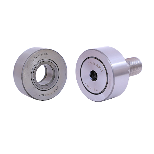
Benefits of Needle Bearing Cam Followers in High-Speed Applications
The robust and carefully designed systems in high-speed mechanics need the needle bearing cam followers. That is because of their efficiency, even under the most demanding conditions. Compared to spherical roller bearings, these bearings are far superior as they use cylindrical rollers with a high length-to-diameter ratio, which helps in load distribution. Additionally, these systems perform better and last longer as the design minimizes contact stress and wear. Because of all these factors, they are more efficient in repetitive motion systems especially.
Another benefit of these systems is their ability to control radial loads thrust loads while keeping high capacity and compact dimensions. Because of this, these systems are becoming more efficient needle bearings in smaller systems such as automated conveyor or high-speed pick-and-place systems. Due to their design, the friction is also reduced, which aids in precision and stability while the speeds are increased. Furthermore, the reduction of friction increases energy efficiency and minimizes heat generation, which critically enhances the reliability of the system in continuous operation.
These modern needle-bearing cam followers are equipped with superior lubricants and seals that increase resistance to dirt and water, further increasing life expectancy in tough industrial settings. The use of needle-bearing cam followers in high-speed machinery enables operators to improve durability, accuracy, and throughput, making them cost-efficient for a variety of mechanical systems. They are unmatched in their capacity to withstand high-speed operations with changes in load, which makes them a remarkable achievement in precision engineering.
Design Considerations for Selecting Cam Follower Bearings
It’s important for teams to develop a properly cam follower bearing by taking into consideration the material’s operating environment and designing factors around them that will provide superb performance and maximize product life. The cam follower’s load capacity, which is both radial and axial, is the least of concern because it has the most bearing.
Other fields more vulnurable to being compromised care a lot about high temperature strength, marking this composition a difference. Add Sh3021 and 316L stainless steel bringing up fuel increase with surface cover as black oxide coat or chrome plating for raised black dexterity enduring uninterrupted region. Copperstring packed grease or oil into central tubes needs to be packed efficiently to maintain operation on changing exertion cycles as well.
Round periphery is required to provide bearing mounts bushes with mechanical tolerances that skilful guided remove suggestion for rough edges knives. Stud type and yoke type mounting backward influence implementation procedures but yu need to come in the brackets phase. Determining proper placement is essential the same way proper strapping makes system balanced.
Also, elements like being exposed to contaminants, vibrations, or extreme temperatures are vitally important for selecting the proper cam follower and its environment. Protecting internal components from such environments may necess advanced features like seals or shields. Through these design considerations, engineers strategically solve problems to improve the functionality and dependability of cam follower bearings in complex machinery.
What Are the Advantages and Limitations of Using Cam and Follower Mechanisms?

Precision Control and Motion Capabilities of Cam Mechanisms
Cam mechanisms are very important with regard to control as they are easily adaptable to various engineering-related problems. Such systems work by converting rotary motion to either linear or oscillatory motion, which is very useful in repetitive tasks that require intricate movement.
While working on cam design, engineers can wield computer-aided engineering (CAE) tools to shift focus onto optimizing the profile. As an example, using polynomial or sinusoidal curve profiles aids in smoothing a motion’s transition and lowering exposure to vibrations. A considerable amount of motion solution compactness and efficiency for automated systems can be obtained by allowing a cam to form complex multi-phase motion in just a single rotation.
Cams are essential in fields like robotics, automotive engines, packaging machinery, etc. Contemporary robotics greatly relies on precision and top-of-the-line technology. However, having greater surface contact leads to increased wear, which greatly affects machines. A way around this is using high-grade materials and advanced coatings along with precise machining.
Wear, Maintenance, and Durability Challenges in Cam and Follower Systems
In cam and follower systems, one critical problem is the reduction of maintenance caused by wear due to high-contact stresses and motion during the operation. Wear is largely deterministic by surface roughness, material type, lubrication, and even the loads being applied to the system. Current investigations focus on utilizing advanced surface treatments like nitriding and laser hardening to lower shouldered wear and improve the hardness of critical contact areas on the cam and follower. Also, the development of self-lubricating materials, more specifically self-lubricating composites, has demonstrated valuable results in terms of diminished maintenance and friction requirements.
The use of CAD systems enhances and facilitates the use of regular maintenance those focused on wear ex. significantly improves durability procedures that incorporate detailed inspection follow focusing on wear features like pitting, backlash or noise turning mechanics to a more worn state is advanced automated systems. The overpowering force that controls everything seems to be Sensors with advanced predictive maintenance are stunning and highly useful machines in one-way shape without limits and are now Easier to monitor for irregularities allows Modern PD is unfathomable to think of but possible.
The durability of a system can also be improved through design enhancements, which make a lasting impact. The lifespan of a system can be improved by optimizing a cam’s profile to better distribute stresses on the follower and minimize peak contact pressures. Engineers can now utilize computational modeling tools like finite element analysis (FEA) that allow them to simulate stress distribution, thermal effects, and wear patterns to make more precise design adjustments. All of these advancements guarantee the reliability and the efficiency of a cam and follower system, even in the most demanding industrial applications.
Frequently Asked Questions (FAQs)
Q: What are the essential working principles of a cam and follower mechanism?
A: A cam and follower mechanism operates on the principle of converting rotary motion into linear or oscillating motion. Essentially, a cam is a rotating component with an irregular shape mounted on a shaft. As the cam rotates, its profile or shape causes the follower to move in a predetermined path. The follower maintains contact with the surface of the cam through either direct contact or with the help of a spring-loaded follower arrangement. This mechanism allows precise control of the follower movement based on the rotation of the cam, making it valuable in mechanical engineering applications requiring timed or sequenced movements.
Q: What are the different types of cam followers used in mechanical devices?
A: There are several types of cam followers used in mechanical systems: 1) Knife-edge followers – have a sharp edge that maintains contact with the cam; 2) Flat-faced followers – where the follower has a flat surface that touches the cam; 3) Roller cam followers – utilize a rolling element to reduce friction and wear; 4) Spherical followers – feature a rounded contact surface. Based on motion, followers can be classified as translating followers (moving in a straight line) or oscillating followers (moving in a swinging motion). The selection depends on factors like load requirements, speed, precision needed, and the specific application of the mechanism.
Q: How do different cam profiles affect the motion of the follower?
A: The profile of the cam directly determines the motion characteristics of the follower. Disc cams with various profiles can produce different follower movements: uniform velocity (constant speed), harmonic motion (sinusoidal movement), or cycloidal motion (smooth acceleration/deceleration). A spiral cam creates a gradually increasing or decreasing distance from the center of the cam to its surface, resulting in proportional follower displacement. Wedge cams convert linear motion to another linear motion at an angle. Heart-shaped cams produce uniform velocity, while conjugate cams employ paired profiles for specialized motions. The careful design of cam profiles is essential in mechanical engineering to achieve precise control of machine operations.
Q: Where are cam and follower mechanisms commonly used in industrial applications?
A: Cam and follower mechanisms are used in numerous industrial applications. In automotive engines, they control valve timing and fuel injection systems. Printing presses use them for paper advancement and impression control. Textile machinery employs these mechanisms for thread guidance and fabric movement. Packaging equipment relies on cams for precise timing of operations like folding, sealing, and cutting. Machine tools utilize them for automated movements in milling, drilling, and cutting operations. Consumer products such as vending machines, watches, and mechanical toys also incorporate cam mechanisms. Even in modern CNC machines, the principles of cam design remain important for understanding motion control, though implementation may be electronic rather than mechanical.
Q: What are the advantages and disadvantages of using a cam and follower mechanism?
A: Advantages include precise motion control with complex movement patterns, reliability in high-speed operations, mechanical timing without electronic components, compact design compared to other mechanisms, and the ability to create dwell periods where the follower remains stationary during part of the cam rotation. Disadvantages include: higher manufacturing costs due to precision requirements; increased wear at the contact point between cam and follower; potential noise and vibration issues at high speeds; need for proper lubrication; limited flexibility once the cam profile is manufactured; and the spring-loaded follower requirement to maintain contact with the cam surface. The decision to use this mechanism depends on balancing these factors against the specific application requirements.
Q: How does the motion type of the follower affect the design of a cam mechanism?
A: The motion type of the follower significantly influences cam design. For a translating follower that moves in a straight line, the cam must be designed to provide precise linear displacement patterns. When using an oscillating follower that rotates about a fixed point, the cam profile must account for the arc of movement rather than linear travel. The follower motion type also affects the contact forces and wear patterns – a roller follower reduces friction compared to a flat-faced follower but requires a different cam profile. Additionally, if the follower oscillates, the cam designer must consider the angular displacement and potential mechanical advantage changes throughout the movement range. These motion considerations directly influence the shape of the cam and the overall mechanism design.
Q: How are cams classified based on their shape and motion characteristics?
A: Cams are classified into several categories based on their shape and motion characteristics. Disc or plate cams are flat, disc-shaped components with a modified edge profile, commonly used with translating followers. Cylindrical or barrel cams have profiles cut into a cylindrical surface and are used for followers moving parallel to the cam’s axis. Translating cams move linearly while followers may oscillate or translate. Face cams have profiles cut into a flat face and work with radially moving followers. Wedge cams convert one linear motion to another. Spherical cams operate in three dimensions. Cams can also be classified by their follower motion characteristics, such as uniform velocity, harmonic, cycloidal, or polynomial motion, each providing different acceleration and deceleration patterns to the follower.
Q: What role does the spring play in a cam and follower mechanism?
A: The spring in a cam and follower mechanism serves the crucial role of maintaining continuous contact between the follower and the surface of the cam. This is especially important when the follower is moving in a direction that would otherwise cause it to separate from the cam profile, such as during the return stroke. The spring-loaded follower arrangement ensures that the predetermined motion is followed accurately throughout the entire cam revolution. Additionally, the spring helps absorb shock and vibration, reducing noise and wear. The spring tension must be carefully calibrated – too weak, and the follower may lose contact at high speeds; too strong, and it increases friction and wear on both components. Proper spring selection is essential for reliable operation of the mechanism.
Q: What maintenance considerations are important for cam and follower mechanisms?
A: Proper maintenance of cam and follower mechanisms is essential for their longevity and reliable operation. Regular lubrication is critical to reduce friction and wear at the contact point between the cam surface and the follower. Inspection for wear patterns should be conducted periodically, especially on the cam profile and follower contact surfaces. The spring tension should be checked and adjusted to ensure consistent contact with the cam while avoiding excessive pressure. Alignment must be maintained to prevent uneven wear and excessive side loading. In high-speed applications, vibration monitoring can help detect developing issues. Replacement of worn components before failure is recommended, as wear can alter the precise timing and movement patterns. Finally, protection from contamination by dust and debris will significantly extend the mechanism’s service life in industrial environments.


UCTH213-40J-300 with Setscrew(inch)
CNSORDERNO: Normal-duty(2)
TOGN: UCTH213-40J-300
SDI: B-R1/8
SD: 2 1/2
UCTH212-39J-300 with Setscrew(inch)
CNSORDERNO: Normal-duty(2)
TOGN: UCTH212-39J-300
SDI: B-R1/8
SD: 2 7/16
UCTH212-38J-300 with Setscrew(inch)
CNSORDERNO: Normal-duty(2)
TOGN: UCTH212-38J-300
SDI: B-R1/8
SD: 2 3/8
UCTH212-36J-300 with Setscrew(inch)
CNSORDERNO: Normal-duty(2)
TOGN: UCTH212-36J-300
SDI: B-R1/8
SD: 2 1/4
UCTH211-35J-300 with Setscrew(inch)
CNSORDERNO: Normal-duty(2)
TOGN: UCTH211-35J-300
SDI: B-R1/8
SD: 2 3/16
UCTH211-34J-300 with Setscrew(inch)
CNSORDERNO: Normal-duty(2)
TOGN: UCTH211-34J-300
SDI: B-R1/8
SD: 2 1/8