Exploring Different Types of Cams and Followers: A Comprehensive Guide to Cam and Follower Mechanisms
Cams and followers are fundamental mechanical components that are widely utilized in various systems to convert rotary motion into reciprocating or oscillatory motion. These mechanisms play a critical role in the design and functioning of numerous machines, enabling controlled motion generation and transmission. From automotive engines to industrial machinery, their applications span an extensive range of industries. This guide aims to provide a detailed overview of cams and followers, exploring the different types available, their operational principles, and the specific use cases for each. By understanding these mechanisms, engineers and hobbyists alike can better appreciate their significance in modern mechanical designs and make informed decisions in selecting the right type for their applications.
What are the key considerations in choosing a cam and follower combination?
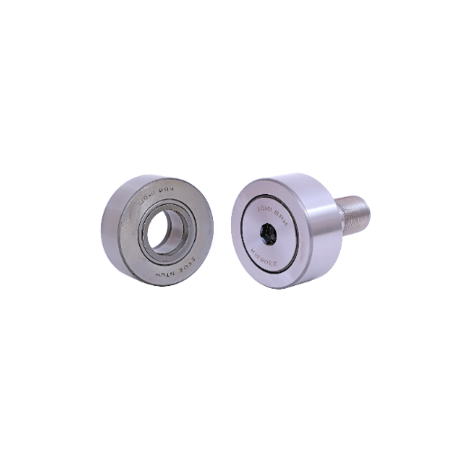
Evaluating the cam profile and its effect on follower motion
- Cam Profile Shape: The cam can be flat, radial, or cylindrical. The shape of the cam determines Shclossen’s Folwer’s motion, which could be simple harmonic, uniform acceleration, or dwell motion. The selection of the cam shape would be based on the desired follower motion to be achieved in the mechanism.
- Lift and Stroke Requirements: The lift or the maximum displacement of the follower needs to be proportional to the functional needs of the application. This is directly proportional to the height and the curvature of the profile.
- Surface Velocity and Acceleration: We examine the velocity and acceleration diagrams while cam profile for optimally. With everything considered, there is always a need to reduce excessive wear, noise, and dynamic loads on the mechanism. It is also easier to work with less aggressive uniform accelerations due to most often shedding stress focus.
- Material and Surface Finish: Both the cam and follower material need to withstand operating stress without being subjected to too much wear. Finer surface finishes such as smooth contours can eliminate excessive friction or fatigue and help prevent premature parts failure.
- Follower Type: This is chosen relative to the application’s load capacity and the needed degree of motion accuracy. For example, roller followers are often employed in situations requiring high speeds with low friction.
By taking into account these defined factors, I try to make certain that the designed cam and follower system provides the desired motion profile, is reliable in service life, and functions appropriately within certain constraints.
Assessing the constraints of the follower in various applications
While considering the constraints of the follower in different applications, there are a few metrics that I put into a systematic assessment to suit its best performance. An operational load is one of the first considerations and it directly relates to material selection as well as the geometric design of the follower. For example, high-load applications tend to wear out and deform harsher steel or composite materials, so they may need to be made of these materials.
Later on, the velocity and acceleration of the follower are also suffered from the dynamic stresses and vibration displacements. For these reasons, it is important that the follower’s motion can be analyzed in terms of stability and fatigue strength. In other words, the motion should remain in the set boundary conditions of the fatigue strength.
In addition, they are also paying special attention to reduce friction and wear in lubrication requires. In this case, the operating temperature and the environment are of concern. For example, lubricant in high temperature environments or where there is a great chance of contamination needs to perform without degrading.
Finally, I accounted for the geometrical interface of the cam-follower and sought the contact stress and surface finish of the precision essential to enable proper motion transmission. Then, I apply the Hertzian contact stress calculations and check if the design can succeed through several cycles without the surface wearing out or roughening and losing the effective work. The mechanisms of the mechanisms measures follower which ensure the working order well under different conditions.
Matching cam types with appropriate follower designs
For radial (disk) cams, a flat-faced follower or roller-type follower is widely used. These followers have a large contact surface and can deal with different velocities efficiently. In particular, the roller follower has better characteristics in that its friction is reduced, making it ideal for high-speed or high-load operations.
For cylindrical cams, the follower will often be of the knife-edge or spherical type. These are useful for the precise applications which need very little point contact and less space overall. In situations with less speed and less friction, knife-edge followers are more suitable, while more spherical followers which are more durable in greater amounts of angular misalignment are better at reducing excessive wear associated with it.
A barrel or drum cam typically combines roller followers onto their surfaces due to their ability to control the cam geometry accurately while reducing contact friction and wear. The main factors I analyze are the radii of the cam’s profile, hardness of the follower material, and the required lubrication. For example, I estimate the particular Hertzian contact stress and check if it is not too high for both the cam and the follower materials.
Any of these combinations can be made based on speed, load, accuracy, maintenance, and other factors with all the math and material attributes predetermined to suit a specific application. Such accuracy makes sure that the system is reliable, durable, and efficient in cam-follower mechanisms.
How do cam and follower mechanisms work in different applications?
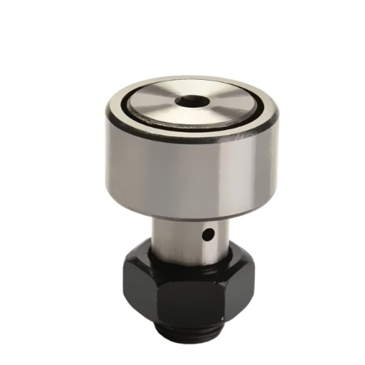
Exploring industrial uses of cam and follower systems
Cam and follower mechanisms are crucial components for many industries since they help to transform rotational movements into linear ones accurately. One of the more common applications is in automated manufacturing systems, which use machine tools or production lines that are driven by motors and operated by cams. In such applications, the most important technical values are the cam profile, which defines the path through which the follower moves, and the dwell period in which pauses of certain events, which are mechanically controlled, need to be maintained. Cams are known to perform at speeds from 100 to 300 revolutions per minute, depending on the loading of the system, its required processing speed, and the effects of the natural rate of the system.
In internal combustion engines, an additional application rests in the regulation of intake and exhaust valves through a cam. In these cases, camshaft angular speed (which is equal to the cylinder head speed) and valve lift height are parameters that need consideration for proper engine performance. These configurations are considering some average value for thermal expansion, material wear resistance, and an acceptable limit value of 0.001 inches for precision tolerances.
Moreover, cam and follower systems find application in textile machines for weft insertion where accurate follower displacement is desired to facilitate cyclic operations at high speeds.
For all applications, the choice of material remains critical, reconciling elements of hardness (for instance, 40-60 HRC for cam surfaces) and wear resistance in order to limit the likelihood of failure during service conditions.
Understanding cam mechanisms in automotive engines
As mechanical systems, cam mechanisms facilitate movement in an automotive engine, controlling the occurrence and timing of each particular valve action autonomously. The rotational movement of the camshaft is transformed into linear movement through the use of cams, facilitating the opening and closing of both the intake and exhaust valves. This stage guarantees the correct inflowing of the air-fuel mixture and outflowing of exhaust gases, which is fundamentally important for the engine power, fuel economy, and emissions.
- Profile Shape: The cam shape determines the lift and duration of the valve, which establishes the level of tuning that can be achieved with an engine. Therefore, aggressive cam profile high-performance engines are designed with the desire of having the cam fully on at higher RPM ranges to allow airflow at the peak.
- Surface Hardness and Material: Cams are manufactured from cast irons or alloy steels and tempered to 45-60 HRC to minimize the damages from high stresses and wear due to the follower’s continuous contact with the follower.
- Timing Valve: The order in which the scandal vent is opened and which the intra-vent is closed takes a portion of the rotation, which is known as timing along the crankshaft.
- Speed of the Camshaft: In a four-stroke engine, camshaft speed is half of crankshaft speed. Synchronization is essential in regulating valve movement within the engine cycle.
Proper coordination among these factors must be carefully designed to circumvent problems like valve overlap inefficiencies, increase in wear and tear, or timing shifts so that the integrity over time can be reliable and engine performance is optimal.
Analyzing cam and follower applications in manufacturing processes
As mechanical systems, cam mechanisms facilitate movement in an automotive engine, controlling the occurrence and timing of each particular valve action autonomously. The rotational movement of the camshaft is transformed into linear movement through the use of cams, facilitating the opening and closing of both the intake and exhaust valves. This stage guarantees the correct inflowing of the air-fuel mixture and outflowing of exhaust gases, which is fundamentally important for the engine power, fuel economy, and emissions.
- Profile Shape: The cam shape determines the lift and duration of the valve, which establishes the level of tuning that can be achieved with an engine. Therefore, aggressive cam profile high-performance engines are designed with the desire of having the cam fully on at higher RPM ranges to allow airflow at the peak.
- Surface Hardness and Material: Cams are manufactured from cast irons or alloy steels and tempered to 45-60 HRC to minimize the damages from high stresses and wear due to the follower’s continuous contact with the follower.
- Timing Valve: The order in which the scandal vent is opened and the intra-vent is closed takes a portion of the rotation, which is known as timing along the crankshaft.
- Speed of the Camshaft: In a four-stroke engine, camshaft speed is half of crankshaft speed. Synchronization is essential in regulating valve movement within the engine cycle.
Proper coordination among these factors must be carefully designed to circumvent problems like valve overlap inefficiencies, increase in wear and tear, or timing shifts so that the integrity over time can be reliable and engine performance is optimal.
What are the advantages and limitations of various cam and follower configurations?
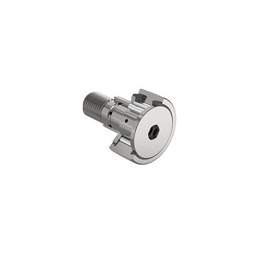
Comparing the performance of different cam shapes
In reviewing various cams, their performance features depend on the design particulars, attributes and specifications. A cam face that is flat is often employed for basic operations because it is simple to transform motion, less complex, and easy to manufacture. Nevertheless, it might be plagued with low precision in the follower supporter’s path control.
Alternatively, a circular or roller cam enables smoother motion and less follower wearing, especially when the speed of operation is very high. This results from reduced friction at their contact point.
Spherical or contoured cam profiles are implemented where great deal of control over follower motion is needed because they enable complex patterns of displacement. On the other hand, they are prone to increased wearing and higher accuracy in their manufacture which increases their cost. Important benchmarks in this case are aimed at evaluating friction coefficients, material durability, and load cycle performance.
In choosing from these configurations, It is best to consider strategically what the application and efficiency will be, and how much it is allowed to spend with these factors without compromising reliable operation of the engine or machine and its further maintenance requirements.
Evaluating the durability and maintenance requirements of follower types
Roller followers are likely to be more durable because contact between the components is often frictional as opposed to sliding; contact is often made by rolling. Chief are hardness measures like Rockwell C, Surface roughness which ought to be below 0.2 microns Ra for smoothness, and rolling contact fatigue life. Periodic checks ought to be undertaken to ensure the correct amount of lubrication and alignment exists to avoid premature wear and pitting.
On the other hand, flat followers, which are more basic in terms of construction, have a greater rate of wearing due to increased friction forces. Features such as the coefficient of friction are critical in determining how long the flat follower will last (falling between 0.1-0.4 depending on the lubrication condition), contact pressure, and materials’ (like heat treated steel or composites) resistance to wear are essential. Maintenance schedules for flat followers include a greater number of lubricant applications and monitoring of surface wear to slow the rate of degradation.
For processes that demand accuracy and long service life, a specific type of follower must be selected that has good fatigue resistance, thermal stability, and deformation characteristics. The employment of advanced lubricants with high film strength and low working viscosity will also increase operational durability and lessen maintenance intervals, irrespective of the type of follower used.
Assessing the precision and repeatability of cam and follower mechanisms
The precision and repeatability in cam and follower mechanisms depend on the manufacturing tolerances, material characteristics, system dynamics, and lubrication efficiency. In regards to the precision, the cam profile must be cut to geometric accuracy of no worse than ±0.01 mm, depending on the application. Also, repeatability can be affected by backlash, wear of the interacting materials, and the dynamic response of the system, which is tuned for low vibration and hysteresis.
- Material Hardness: For operational parts which are subject to considerable wearing, materials of hardness HRC 60 or greater should be employed.
- Surface Finish: The roughness of the cam surfaces and follower contact points should be less than 0.2 micrometers (Ra).
- Dynamic Balancing: The operational speeds should be set to 80 percent of the natural frequency of the mechanism in order to reduce system vibrations.
- Lubrication: At operational temperature and load boundaries, lubricants such as ISO VG 68 or VG 100 would be preferable due to their viscosity grades.
By adhering to these factors, the mechanism can maintain reliable and repeatable performance over extended operational periods.
How do globoidal cams differ from other cam types?
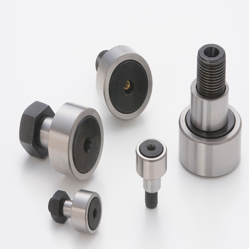
Understanding the unique geometry of globoidal cams
Different from other types, globoidal cams have a three-dimensional design, which allows more complex motioning. Unlike planar or cylindrical cams, globoidal cams have an oscillating worked surface with a cam rotation, and they have a very high compactness because they allow several followers to be positioned at different angles. This is useful where precise rotary indexing is needed.
- Cam Profile Curvature: The contour of the cam must be designed to guarantee smooth contact with the follower without introducing stress concentration which may cause high wear.
- Follower Contact Angle: This angle is almost always optimum at 30 and 45 degrees to guarantee contact force and low slip speeds.
- Material Properties: Allay steels with flow treat at 50-60 HRC for dimensionally stable under load and resist high wear.
- Accuracy of Machining: To engage and disengage the cam and follower, tighter tolerances within ±0.01 mm will guarantee that there is no more than the required gap.
- Lubrication Requirements: The most advanced synthetic greases with a high load carrying capacity offer effective lubrication while preventing excessive abrasive wear and damage due to complex loading paths; however, extreme care must be implemented.
Globoidal cams will guarantee precise, efficient, and rugged motion for high-performance machinery, leveraging any combination of these features.
Exploring the benefits of globoidal cams in specific applications
Globoidal cams are particularly useful in specialized areas because of their level of accuracy, effectiveness, and longevity. For example, in automated assembly systems, their capability to provide synchronized and repeatable motion is crucial in achieving a desired production rate and precision. Inoas robotics, globoidal cams also guarantee accurate positional control, which is crucial for accomplishing complicated tasks.
- High Load Capacity: Hardened materials are always more than enough to withstand deformation because of the cam’s use of optimized profiles. The materials also ensure the maintenance of high forces, such as 50-60 HRC, without enduring any scratches.
- Dimensional Accuracy: Motion transfer is seamless, and engagement errors are avoided with set tolerances within +0.01 mm.
- Lubrication Efficiency: Mid-range effectiveness of synthetic greases reduce any wear and thermal impacts of high-speed operations for a long period.
Through these attributes, globoidal cams’ amplifying use in multiple industries where precise motion control is necessary can be noted.
What are the fundamental principles behind cam and follower motion?
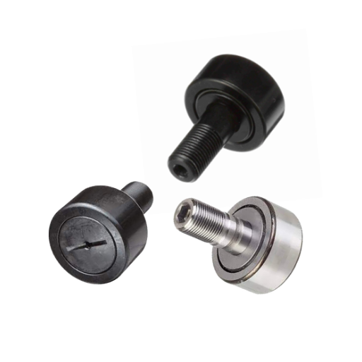
Analyzing the relationship between cam rotation and follower movement
The motion of the cam-and-follower system is dictated by the cam profile, follower type, and intended motion configuration. Each contour of a cam determines if the follower, through which the cam rotates, will undergo linear or oscillatory motion via a contact or rolling interface.
- Cam Profile Geometry: The geometric accuracy of the cam (designed to ±0.01 mm) fulfills the oscillating motion law. It contains the unwanted oscillations or vibrations that are undesirable in the system.
- Angular Velocity Synchronization: Constant standard speeds of the cam, usually maintained at ±0.5%, are ready to control any factors that may cause discrepancies ,such as phase error between input and output movement.
- Follower Characteristics: The material hardness of the follower utilized (50-60 HRC) combined with the surface roughness (Ra ≤ 0.2 µm) causes lower wear and good motion over long periods.
Armed with such factors, the cam-and-follower mechanism maximally translates the precise motion required for automated machinery, engine valvetrains, and robotic applications.
Understanding the importance of contact points in cam-follower interactions
The interface between the cam and follower needs to be handled very carefully for efficient transfer of motion and for the longevity of the mechanism.
- Contact Stress Distribution: The area that interfaces needs to have an appropriate means to allocate stress within aid in preventing deformation. This is done by having a required surface curvature and material matching from the cam and follower.
- Lubrication Efficiency: Sufficient lubrication at these points reduces friction as well as heat and increases life span of the parts. Oils and grease with certain viscosity levels like ISO VG 68 are recommended depending on the operating condition.
- Surface Hardness Comparison: Wear resistance depends on the relative hardness between the cam and follower. For instance, the use of a harder cam together with a slightly softer follower optimizes wear rates thus preventing catastrophic failure in the system.
- Surface Roughness: The interface should have low surface evenness (0.2 µm roughness) that enables the smoothing of interactions and the mitigation of pitting or scuffing after prolonged operation.
Effective management of these factors is important in achieving the required cam follower system precision and reliability while avoiding mechanical failure.
Frequently Asked Questions (FAQs)
Q: What is the working principle of cam and follower mechanisms?
A: The working principle of cam and follower mechanisms is based on the motion of the follower in contact with the cam. A cam is a rotating element with a specific shape or profile that imparts motion to the follower. As the cam rotates, the follower moves according to the cam’s profile, converting rotational motion into linear or oscillating motion.
Q: What are the main types of cams according to follower motion?
A: The main types of cams according to follower motion are: 1. Radial or disc cams: The follower moves in a direction perpendicular to the axis of the cam. 2. Cylindrical or barrel cams: The follower moves parallel to the axis of the cam. 3. Face cams: The follower moves in a plane perpendicular to the axis of the cam. 4. Wedge cam: A translating cam where the follower moves along a linear path.
Q: How are followers classified based on their motion?
A: Followers can be classified based on their motion as: 1. Translating followers: They move in a straight line. 2. Oscillating followers: They rotate about a fixed axis. 3. Roller followers: Have a roller that makes contact with the cam. 4. Flat-faced followers: Have a flat surface that contacts the cam. 5. Spherical-faced followers Have a curved surface that contacts the cam. 6. Knife-edge followers: Have a sharp point that contacts the cam.
Q: What are some common applications of cam and follower mechanisms?
A: Common applications of cam and follower mechanisms include 1. Internal combustion engines (valve timing) 2. Automated manufacturing machinery 3. Packaging equipment 4. Textile machinery 5. Printing presses 6. Vending machines 7. Automotive systems (fuel injection, automatic transmissions) 8. Machine tools (feed mechanisms, indexing devices)
Q: What is the difference between a translating cam and a rotating cam?
A: A translating cam moves in a linear path while a rotating cam rotates about its axis. In a translating cam, such as a wedge cam, the cam itself moves linearly to impart motion to the follower. In contrast, a rotating cam, like a radial or cylindrical cam, rotates around its center or axis to drive the follower’s motion.
Q: How does the shape or profile of the cam affect the motion of the follower?
A: The shape or profile of the cam directly determines the motion of the follower. Different cam profiles can create various follower motions, such as: 1. Uniform velocity 2. Simple harmonic motion 3. Cycloidal motion 4. Parabolic motion The cam profile is designed to achieve the desired follower motion for specific applications, considering factors like acceleration, velocity, and displacement.
Q: What are the advantages of using roller followers in cam mechanisms?
A: Roller followers offer several advantages in cam mechanisms: 1. Reduced friction between the cam and follower 2. Lower wear on both the cam and follower 3. Ability to handle higher speeds and loads 4. Smoother operation and reduced noise 5. Improved efficiency and longer lifespan of the mechanism 6. Better ability to maintain contact with the cam profile
Q: How do face cams differ from radial cams in terms of follower motion?
A: Face cams and radial cams differ in the direction of follower motion: 1. In face cams, the follower moves in a plane perpendicular to the axis of the cam. The cam’s profile is on its face, and the follower reciprocates or oscillates in a direction parallel to the cam’s axis. 2. In radial cams, also known as disc cams, the follower moves in a direction perpendicular to the axis of the cam. The cam’s profile is on its edge, and the follower typically moves in a radial direction relative to the center of the cam.
UCTH213-40J-300 with Setscrew(inch)
CNSORDERNO: Normal-duty(2)
TOGN: UCTH213-40J-300
SDI: B-R1/8
SD: 2 1/2
UCTH212-39J-300 with Setscrew(inch)
CNSORDERNO: Normal-duty(2)
TOGN: UCTH212-39J-300
SDI: B-R1/8
SD: 2 7/16
UCTH212-38J-300 with Setscrew(inch)
CNSORDERNO: Normal-duty(2)
TOGN: UCTH212-38J-300
SDI: B-R1/8
SD: 2 3/8
UCTH212-36J-300 with Setscrew(inch)
CNSORDERNO: Normal-duty(2)
TOGN: UCTH212-36J-300
SDI: B-R1/8
SD: 2 1/4
UCTH211-35J-300 with Setscrew(inch)
CNSORDERNO: Normal-duty(2)
TOGN: UCTH211-35J-300
SDI: B-R1/8
SD: 2 3/16
UCTH211-34J-300 with Setscrew(inch)
CNSORDERNO: Normal-duty(2)
TOGN: UCTH211-34J-300
SDI: B-R1/8
SD: 2 1/8


