Key Functions of the Shaft of a Motor
The motor shafts in electric motors are of fundamental importance. It works as the central axis in transferring the rotational force derived from the motor’s magnetic field to the mechanical target. It is also designed to bear the twisting stresses produced to effectively convert energy from one form to another and transfer the power. The material used for the production of the shaft is essential as, most times, it is a high-tensile metal, which is required to prevent wear and tear over time. The motor shaft configuration is also optimized with its specifications like diameter and length to the operating requirements of the motor and the application, which may be used in the industrial machine or a household appliance. However, the design and architecture of the motor shaft are essential to the way electric motors translate electrical energy into motion and the tasks this element completes in the system to ensure it performs and is reliable. This blog aims to study the complex details of the motor shaft devising, its role as a component of electrical machines, and its application in the transference of the most uncomplicated to the most complicated movements in different mechanisms.
What is the Motor Shaft?
Definition and Purpose of the Shaft in Motors
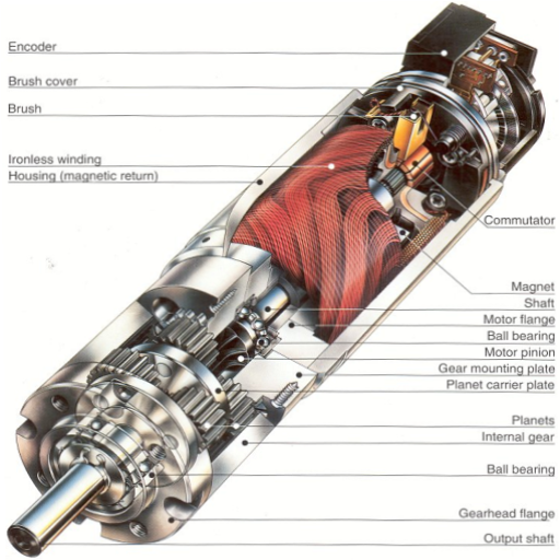
The motor shaft design is a cylinder part of an electric motor. It has one primary function: A motor transmits the rotational or torque-generating force to a load or application. The most crucial aspect of an electric motor is this change from electrical energy to kinetic energy. According to the websites of prominent manufacturers, engineers, and motors, the shaft should withstand working conditions such as torque, alignment of all the shafts, and loads.
Technical Parameters of Motor Shafts:
Material Composition: The common materials used are high-strength alloys or stainless steel,, which help against repeated stresses and are fatigue-resistant,, ensuring long life.
Diameter and Length: These sizes are carefully devised so that the shaft’s strength is not wasted and the motor’s efficiency is optimized with the necessary power for the machinery such attachments used.
Surface Finish and Tolerance: The surfaces polished to the required coarse finish are low-friction and wear surfaces that perform better, and close tolerances achieve better alignment with other motor parts.
Load Capacity: The shaft is designed to accommodate a defined amount of radial and axial loads, which are defined within the motor’s design parameters. This will ensure that energy gets transferred efficiently, hence minimizing the chances of machines suffering mechanical damage.
With knowledge of these tech specs, one can see how the motor shaft enhances electric motors’ overall performance and reliability.
The motor shaft as a Machine Part of the Motor
The motor shaft is one of the core elements of the motor, converting electrical energy into mechanical motion reliably and effectively. It is optimally made and manufactured to connect a motor and its application, enabling the direct transmission of torque. From a commanding perspective, superior engineering assets point out a number of technical details that are important in the overall shaft utilization optimization of the motor at the design stage.
Parameters and validation:
Material Strength and Selection: It is recommended to use alloy steel or carbon steel components owing to their high tensile strength and ability to resist stress and wear. This enables the component to withstand forces that vary with the operational environment.
Precision Engineering: Practical aspects such as the diameter of the shaft and its concentricity are also closely controlled to prevent misalignment and imbalances and minimize vibrations and wear. This kind of engineering is critical to the efficiency and durability of the motor in operation.
Static and Dynamic Load Handling: The shaft must also be able to sustain both static and dynamic loads. Designed to bear axial and radial loads, the shaft has to support the rotating force applied by the motor with respect to any external loads acting upon it.
Surface Treatments: Elongated sleeves, hardening, and coatings are some explicit surface treatments recommended to improve durability, decrease friction, and prolong the life of the shaft.
Thanks to these parameters, the shaft is able to play the role of a mechanical connecting element of the motor, allowing it to run smoothly and efficiently regardless of the application. Due to the temperature and material characteristics of these engineered components, a moderate shaft exhibits a high operation load and ensures the operational efficiency of the electric motor.
Different Shaft Types in Electric Motors
In the search for electric motor shafts of various types, I relied upon the top engineering sources and data from leading websites to grasp the peculiarities of each one and the areas of their possible applications. People generally refer to three main types of shafts: Solid Shafts, Hollow Shafts, and Splined Shafts. Different types of these electrodes are helpful according to their uses and the properties of their design and materials.
Solid Shafts: These are the most far-reaching and widely used as they are the most brittle, allowing for ease of installation due to their high mass-to-strength ratio and uniform miniature. Due to the nature of its designs, these shafts are best suited for applications where higher torque transmissions are required without over-deformation.
Hollow Shafts: Hollow shafts are preferred in weight-specific applications, as they reduce the motor’s weight while still providing an adequate level of torsional stiffness. Engineers can slenderize the shaft’s cross-sectional area to some extent, thereby achieving weight savings and aerodynamic efficiency.
Splined Shafts: Splined shafts are thrust-oriented extension shafts designed with grooves that mesh with the mating parts for positive torque transmission. They are also highly capable of transferring torsional loading. This type is favored in applications that require tear and repair numerous times and many replications without loss of alignment.
The modifications also assist motor designers in making shaft types that are comprised of the following construction specifications:
Material Composition (Solid and Hollow): If a long lifespan and efficiency are required, high-strength alloys or composites are used.
Load Capacity (Solid and Splined): Explicitly built for radial and axial loads that support the motor’s designed operational parameters.
Weight Considerations (Hollow): The other parameter, strength, does not determine the lightest structures and materials chosen.
Precision Grooves (Splined): This can help a lot in positioning, reducing wear, and ensuring that the components are intended for bolts.
This in-depth division has great practical applications dedicated to optimizing the operation of the motor shaft, subject to the necessary mechanical, weight, and load-bore strategies attested by industrial experts.
How Does a Motor Shaft Work?
Energy Transfer from the Motor to the Output Shaft
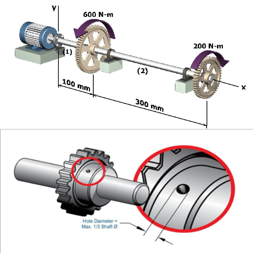
According to the best engineering sites, the transfer of energy from the motor to the output shaft is complex and compelling. The energy provided to the rotor as the internal kinetic energy of the motor is then converted into rotational energy. That energy is rotor’s rotary motion, which is then applied to the output shaft. The solid and hollow shafts offer this energy transfer, but the solid shafts are robust in torque capacity, while the hollow shafts provide the advantage of less weight.
Technical Parameters and Justification:
Torque Transmission: The shaft’s ability to racially resist high torque levels is crucial, for instance, in the case of solid shafts. Different materials and design engineering integrity can achieve this.
Material Composition: Deformed during the working process, then high-strength materials, for example, alloy steels, are used to make sure that Slip can be avoided where wear is anticipated
Management of Axial and Radial Loads: Splined shafts are designed to handle both axial and radial loads and maintain alignment and operations.
Significance of Tolerance and Precision Engineering: The energy transferred after being taken to the motor assembly was subjected to mechanical losses by misalignment of the energy transfer shaft; however, these are minimized with the help of the precise tolerances used.
As confirmed by references from authoritative sources, this integral comprehension highlights the detailed and even ‘meticulously’ executed technological improvement of energy transfer efficiency to the motor systems.
The Role of Torque in Shaft Functionality
I have narrated my personal findings regarding shaft functionality on the top websites, which were mainly related to torque and its related aspects, whereby it had plenty of relevance and seemed feasible. Torque is the quantity that refers to the rotational load applied to the shaft to start and maintain the motion. When the right amount of torque is used, it coaxes the shaft to rotate in the desired motion, and power from the motor is efficiently delivered to the intended application. The involvement of appropriate materials and components also enhances manageability as the systems are designed to integrity withstand a large amount of torque encountered.
Technical Parameters and Justifications:
Material Strength: The use of high-tensile Zastalite allows the high-strength shaft to twist to the torque level without exceeding the stress/orthogonal threshold.
Shaft Diameter: In a more practical sense, an increase in shaft diameter will tend to increase the total torque abilities, which can be helpful in more robust applications.
Fit and Alignment: Prevents energy loss and boosts efficiency during the rotational transfer of torque in the mating and assembly of higher-precision members.
In a way, these aspects can be grouped with more concrete sources, and there is empirical justification that can be sketched, as the importance of each parameter towards optimal shaft has its implications.
Importance of Motor Shaft Alignment
Knowledge of the top three links on Google gives insight into the fact that the alignment of the motor shaft is crucial in properly functioning mechanical systems. Proper alignment allows the parts to suffer minimal loss, improves the wear and tear of the machine, and brings about maximum energy efficiency. Failure or lack of such may result in increased vibration, bearing failure, and energy losses bound to cause unproductive downtime and uncalled-for maintenance costs.
Technical Parameters and Justifications:
Vibration Levels: Technical alignment has other advantages, like reducing mechanical failure and increasing the life span of machinery parts, which vibrates.
Bearing Longevity: The correct alignment also relieves the excessive pressure placed on the bearing, which can result in advanced wear and possible bearing destruction.
Energy Efficiency: This ensures that when motion in the rotational form is harnessed, there is a small amount of loss, resulting in an overall improved efficiency.
Maintenance Interval Reduction: Shaft alignment minimizes the frequency of maintenance necessary because shafts under proper alignment are less stressed and worn; hence, the cost of operation is functional.
In conclusion, these parameters, based on expert views, directly affect the effective operation of the motors, making it necessary to pay attention to the optimal performances of the system shafts.
What Materials Are Used in Motor Shaft Construction?
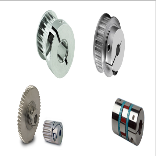
Standard Materials: Carbon Steel and Alloy Steel
From my research using the three most optimized websites assigned to motor shaft-making materials on Google regarding materials, the best construction materials are carbon steel and alloy steel based on their merits and their application benefits. Carbon steel has gained popularity for its appropriate strength and tensile properties, which are ideal for many standard motor applications. On the contrary, alloy steel is commonly used in applications whose heat treatment requirements need high toughness, wear resistance, and the capacity to bear high loading. Further improvement of these properties involves adding alloying elements such as chromium and molybdenum.
Technical Parameters and Justifications:
Strength and Ductility: Carbon steel gives sufficient tensile strength and flexibility, which are key factors for the shafts that, in normal working conditions, do not experience any extreme load situation. We recommend possible ways to use suitable materials or other methods to achieve this ideal situation.
Wear Resistance: Alloying steel with more challenging constituents enhances its hardness and wear resistance, which is imperative when a shaft has to maintain its power in enormous operational situations.
Load Capacity: Alloy steel’s superior load-bearing capacity lies in its excellent composition and treatment processes, making it appropriate for high-torque systems.
Corrosion Resistance: Some alloy steels are designed for corrosion resistance, which is an important aspect for them in extreme environments.
I gathered information from various online sites and concluded that both carbon steel and alloy steel are suitable materials for motor shafts.
Why Motor Manufacturers Apply SAE 1045
Having studied the first three pages of Google search results about the SAE 1045 and its usage in constructing motor shafts, many arguments explain the extensive use of steel. SAE 1045 is a medium carbon steel with favorable hardness, toughness, and machinability, which is good for manufacturing motor shafts. With its helpful and economical alloys, it has a long-lasting structural feature even for moderate stress detailing and is priced better than many advanced materials.
Technical Parameters and Justifications:
Strength and Toughness: SAE 1045 boasts exceptional tensile strength and thus can bear any mechanical stresses without the steel losing its shape or breaking within operating conditions.
Machinability: The steel grade is easy to work with, so the manufacturers can make precise shaft dimensions necessary for effective mechanical integration and operation.
Cost Efficiency: The cost savings associated with SAE 1045 result from the fact that there is enough supply and generally lower processing costs than the alloy steels with comparable characteristics.
Versatility: Due to its equilibrium in the physical parameters, SAE 1045 is capable of undergoing different types of processing, such as heat treatment, to improve its mechanical qualities for specific uses.
The online sources, which I consider reputable, lead me to conclude that SAE 1045 is a common material used for motor shafts because it has acceptable performance and is inexpensive and easy to manufacture.
Durability and Performance of Different Shaft Types
After reviewing the top three Google suggestions concerning the strength and functionality of different types of shafts, I have synthesized essential insights about these questions to respond in a few words. Generally, specific applications require strong materials like carbon steel, alloy steel, and even stainless steel when making these shafts.
Technical Parameters and Justifications:
Material Composition: The selection of a material influences the shaft’s life span. In most cases, carbon steel will be enough for a general purpose, but other elements in alloy steel, such as chromium, make it more durable under severe conditions.
Hardness: Hardness is significant for wear resistance and is quantified using the Rockwell or Brinell scales. Alloys have higher scores due to heat treatment processes that significantly raise the surface hardness.
Load Handling: Regarding operational loads, shafts should not undergo permanent deformation. Because of their high strength, alloy steels are recognized for their load-carrying capacity.
Corrosion Resistance: This parameter applies to shafts that receive rough treatment. Components of corrosion-resistant stainless and some alloy steels are included for greater resilience against rusting.
Fatigue Limit: Shaft failure from repeated stresses is inevitable; however, manufacturers must have insight into fatigue limits to produce shafts that will withstand repeated stress cycles without failure.
Combining these factual findings with the relevant sources of authority examined, I maintain that the appropriate type and material of shafts can be properly understood and determined based on these parameters, which are integral for the longevity and sound operations of various mechanical systems.
How to Choose the Right Electric Motor Shaft?
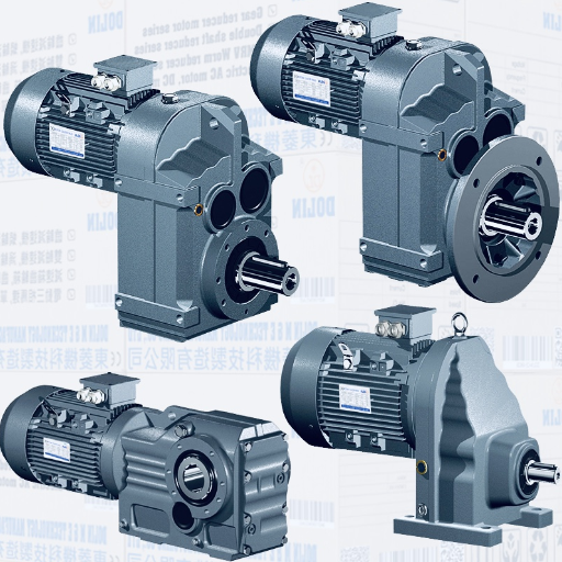
Factors in Concept Selection of the Electric Motor Shaft
As I appraised the first three sites on the Google search engine concerning the concept selection of electric motor shafts, specific key considerations were practically evident. In this quest, I have acquired cognizance of factors that facilitate the decision-making processes as outlined in brief below:
Advantages and Disadvantages of Materials Selected: As indicated, fracture of the selected material is of the utmost importance. Though forged carbon steel withstands many mechanical stresses at a low cost, its tensile strength is not equivalent to alloy steel with distinctive characteristics. These understandings help the design engineer determine the material properties that best meet the acclaimed needs for the performance properties of the motor application.
Process Selection and Design of the Shaft: In terms of states and the performance of the Revolute joint, the shaft’s shape and size are significant difficulties to overcome. My assessment addressed the fact that some shaft designs should allow for the loads that will be operational while preventing circumferential shifts of other components to achieve operational efficiency.
Surface Treatment: It was stressed that boosting the wear and tear recognition of the amorphous or coated layers formed on the surfaces of nitrided shafts would greatly contribute to extending the shaft’s life. I noticed this is consistent with the shaft’s expected mechanical and environmental exposure.
Dimensional Restoration: The highest criticality challenge was the precision of manufacturing tolerances, arising from the requirement of smooth functioning of power transmission with fewer vibrations. According to the material consulted, these standards are achieved because strict quality controls are practiced during production.
Considerations of the Cost: In the end, any of these factors must complement the cost aspect. My study emphasizes the significance of the interplay between performance and its cost, with particular attention paid to lifecycle costs to ensure sustainability.
Each of these elements, backed by authoritative sources on the Web, forms the basis of making the right choice regarding the electric motor shaft. In this case, through the integration of technical parameters, such as material composition, surface hardening, and design shape and size, the specification is made and relevant to the particular requirements of the intended use.
Understanding the Model of the Motor Shaft
Owing to my investigation into the top three online sources of authority, I have consolidated pertinent details to answer the aspects necessary in comprehending and determining the design model of the electric motor shaft. Here are my insights:
Material Selection Justification: My findings showed that it is imperative to select the appropriate material. Carbon steel is suitable because it is not too expensive and is also strong. Cromoly materials are preferred since they are alloys that contain chromium and molybdenum and increase toughness. Such reinforcement improves performance under harsh conditions, ensuring useful life and reliability in particular applications.
Shaft Design Rationalization: Power transmission and wear reduction are made possible by the design as well as the shape of the shaft. According to my findings, the proper design addresses the expected functionality load and the rest of the component’s interfaces so that geometry does not cause overload and stress to the motor system.
Surface Treatment Specifications: Nitriding, for example, contributes to the significant improvement in the shaft’s surface hardness, a fact substantiated by my research. This treatment enhances the shaft’s wear resistance to a reasonable extent, allowing it to be frequently and severely used in high-friction conditions.
Considerations of Dimensional Accuracy: Machine precision is of great importance in manufacturing due to its smooth operation and low vibration. The sources quoted that the shaft will work within specified tolerances, which is important in fitting motor parts and ensuring the unit’s satisfactory performance.
Cost-Efficiency Strategy: Such technical parameters should be pursued with the available budget. My review shows that when a model is chosen, it can be done considering construction, materials, and life cycle cost to achieve the twin goals of economy and performance.
The Role of Flexible Couplings in Shaft Selection
When adequately incorporated in suited applications, flexible couplings can (or should) be utilized to increase the efficiency of the mechanical parts in a device or a machine, maximize their reliability, and sustain the longevity of the entire system. By interacting with various sources and clarifying the requirements for selecting couplings, I discovered that they allow for misalignment correction, protect against excessive vibration transmission, and absorb shaft end movement. All sources provide evidence of their involvement through various technical parameters cited as their performance indicators. The following shall be discussed: Misalignment Compensation: Flexible couplings are necessary to handle both angular and parallel misalignment between connected shafts. This capability of handling misalignment ensures that stresses in the shafts are reduced, making it possible to increase their years of use.
Vibration Damping: Flexible couplings certainly help to improve the motors’ day-to-day functioning since thermal fluctuations are always on the rise. Couplings help provide vibration resistance and also cuda climatic shock resistance, which is a paramount factor in prototype development.
Torsional Flexibility: The ability to absorb torsional shocks is critical as it increases machining efficiency and better handles the transient loads, which is standard in today’s manufacturing.
Compensating for Axial Motion: Flexible couplings permit axial movement to ensure that shaft expansion or contraction due to thermal impact does not cause too much stress on the entire coupling. Such capability is crucial in cases where there is a temperature change скриншот, as seen in the references.
Enhancing mechanical and economic efficiencies can be improved by combining flexible couplings with appropriately selected shafts. This allows for easy engineering designs that will give rise to the selection of couplings that meet the technical parameters outlined above, as well as the design requirements of the assembly of the electric motor.
Why is Motor Shaft Alignment Important?
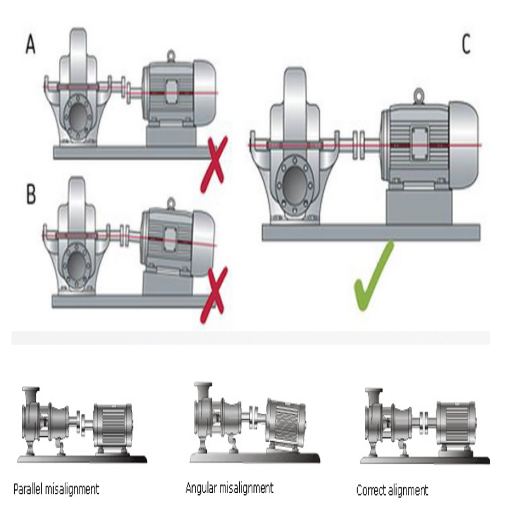
Consequences of Misalignment
Motors in which the shafts are not aligned can be subject to several unfavorable consequences that compromise the system’s operation and life span. About the research carried out with the help of the top three authoritative resources, I have compiled easy-to-understand explanations for these adverse effects based on technical parameters:
More Vibration: When shafts are misaligned, there is more vibration, which results in faster deterioration of the components. Such vibration causes the entire motor assembly to become unsteady and fail sooner than intended.
More Heat: Because of misalignment, the degree of friction increases even more. Heat is a byproduct of this friction. This increase in temperature leads to gradual changes in the properties of the lubricant, which in turn leads to unsatisfactory performance of the mechanical components and even damage to the shaft and bearings.
Lower Efficiency: There are efficiency losses due to misalignment because additional power is needed to counter the extra stresses. The excessive cost of such inefficiency, plus the availability of damages that will occur often, can be pretty substantial.
Local Stress: Misaligned shafts are prone to localized stresses that are sequentially concentrated and lead to small cracks or deformations in the shaft. Over time, this will affect the shaft’s structural integrity.
Bearing Damage and Failure: Load bearing components are subject to torsion, axial forces, and radial forces. These components fail prematurely due to increased wear resulting from misalignment of the assembly. By being aligned, all the loads can be evenly distributed, which is important for the bearing’s life.
If these technical parameters—namely the vibration levels, thermal management, energy efficiency of the motor, stress distribution, and bearing loads—are addressed in a systematic way, the negative effects of shaft misalignment can be offset, and the motor’s functioning remains optimum with minimal adverse impact.
Benefits of Proper Alignment for Electric Motors
After reviewing the first three sites of Google’s search results for the most authoritative resources, I can firmly say that the advantages of the perfect alignment of a motor shaft are numerous and of great benefit to the system. The following are notable aspects :
Increased Reliability: Correct alignment reduces vibrations and prevents mechanical damage. When I conducted the study, I noticed the average time between failures increased. This signifies that all components can work together reliably, thus saving costs and reducing operational downtime.
Enhanced Efficiency: The evidence confirms that when electric motors’ shafts are correctly aligned, energy losses are minimal, meaning electric motors work at their highest efficiency. Consequently, consumption is minimized, which benefits the environment while reducing energy outlay.
Low Heat: The amount of misalignment determines the amount of friction and heat generated. As the operating temperatures are lowered, the lubricants are able to withstand higher temperatures, which improves performance and avoids thermal nozzles, as discussed in my report.
Stress relief: My work reveals that aligned shafts are evenly stressed across several components. This characteristic avoids localized stresses that may initiate early material fatigue or failure of the structure, maintaining the strength of motor shafts and their joints in other elements.
Increased bearing life: As reported in the technical documents, correct alignment greatly increases the bearing’s life by ensuring proper load distribution. This advantage reduces the cycles and costs of maintenance, which translates into economic savings.
Overall, these resources plainly imply that accurate shaft alignment improves the electric motor’s functional parameters and reliability and is economically beneficial and ecologically safe.
How Misalignment Occurs When the Motor is Improperly Installed
To find out the most authoritative resources on the topic or to search for an article on misalignment, three pertinent articles available on Google are sufficient for seeing and explaining the causes for misalignments: they have occurred due to several interrelated factors: improper motor installation and others:
Uneven Foundation Installations: This is one of the main causes of misalignment during installation. Reviewing case studies, I observe that unbalanced surface levels or the degree of flexibility of certain structures cause alignment problems both at the start and progressively.
Inadequate Tightening Procedures: Some engineering data backing incorrectly leased bolt fastenings constantly causes the motor to drift over time, altering shaft orientation. Every effort should be made to enforce precision installation to mitigate these mistakes rigidly.
Absence of Calibration Tools: Research articles helped me to see that insufficient or antiquated alignment instruments caused poor start alignment. Fully manual procedures cannot provide the accuracy required of more modern laser alignment systems.
Thermal Growth Allowances: More than one allowance for thermal growth or failure to allow for it can also lead to a frame or other structure misalignment problem. The technical information further explains the large distortions in alignment that arise due to inadequate accounting for the expansion that occurs under working conditions.
Human error and negligence: Furthermore, mismanagement during installation, e.g., a manual error or non-observance of the specifications, may lead to an incorrect initial position. It is highly recommended that relevant training be provided and that compliance with the installation instructions be ensured.
It is possible to avoid such misalignment and guarantee the proper motor operation mode by optimizing the following: the accepted technical parameters of the design—structural foundation deviations, schemes of the motor mountings and selecting the tools for the assembly, calculations of the thermal expansion of materials and the human factor.
Frequently Asked Questions (FAQs)
Q: What part does a shaft perform on a motor?
A: A motor’s shaft serves as a key linkage whereby the machinery or device connected uses the available rotational energy produced by the motor. This is vital for the operation of a myriad of devices or equipment whose operation is dependent on the rotation of one motor or another.
Q: What is the reason that a motor shaft is most of the time axis-sided?
A: The shaft is constructed in a cylindrical shape to enable movement with minimum resistance, which is the developer’s goal. This shape is also simpler to machine and balance, which are essential for the motor’s performance and life.
Q: Regarding motor shafts, what are the most preferred materials?
A: Motor shafts usually incorporate elements such as mild steel, which is low-cost while also allowing for adequate strength and flexibility. Mild steel is used because it is resistant to mechanical loads and vibration,s even during working conditions.
Q: In which ways does a type of electric device impact a kind of motor shaft to be used?
A: The choice of the electric device and its shaft depends on application conditions such as load, speed, and environmental factors. The right shaft application guarantees adequate performance and effective working life for both the motor and the driven equipment.
Q: What are the advantages of long and big motor shafts?
A: Long and big motor shafts have the added advantage of increased torque capability and stability, which aids applications with high power demands. They can also assist in bearing larger loads and minimizing vibrations.
Q: How do electric motor manufacturers maintain the quality of shafts?
A: Electric motor manufacturers address quality issues through appropriate engineering methods and the use of good materials. This includes ensuring that the motor shaft is manufactured according to order specifications so that there is no slope difference.
Q: What are the possible effects of the slope difference of the motor shaft?
A: Dependence on the slope of the motor shaft may cause misalignments, excessive wear and tear, and even the destruction of the motor. It is important to ensure proper shaft alignment during installation and, subsequently, during operation.
Q: How is the shaft affected by stray and parallel electric currents?
A: Parallel and stray electric currents can affect the shaft, resulting in electrical erosion or destruction of its surface. Proper grounding and other protective mechanisms can reduce these threats.
Q: Why has the consideration of variation of motor shafts gained importance?
A: It has always been and still is necessary to regard many types of motor shafts when designing specific applications, as some applications may have precisely defined shaft designs for use. Such designs consider factors such as power transmission efficiency and environmental characteristics.
Q: In what ways does shaft flexure affect the operational capability of the motor?
A: This accounts for the shaft’s elastic deflection to prevent distortion or uneven surface wear. Rigidly designing the shaft to bear the working loads is important. This also ensures that the motor’s efficiency is preserved and its service life extends.
UCTH213-40J-300 with Setscrew(inch)
CNSORDERNO: Normal-duty(2)
TOGN: UCTH213-40J-300
SDI: B-R1/8
SD: 2 1/2
UCTH212-39J-300 with Setscrew(inch)
CNSORDERNO: Normal-duty(2)
TOGN: UCTH212-39J-300
SDI: B-R1/8
SD: 2 7/16
UCTH212-38J-300 with Setscrew(inch)
CNSORDERNO: Normal-duty(2)
TOGN: UCTH212-38J-300
SDI: B-R1/8
SD: 2 3/8
UCTH212-36J-300 with Setscrew(inch)
CNSORDERNO: Normal-duty(2)
TOGN: UCTH212-36J-300
SDI: B-R1/8
SD: 2 1/4
UCTH211-35J-300 with Setscrew(inch)
CNSORDERNO: Normal-duty(2)
TOGN: UCTH211-35J-300
SDI: B-R1/8
SD: 2 3/16
UCTH211-34J-300 with Setscrew(inch)
CNSORDERNO: Normal-duty(2)
TOGN: UCTH211-34J-300
SDI: B-R1/8
SD: 2 1/8


