Maintenance Tips for Extending Cam Follower Roller Lifespan
Following appropriate practices to equip your cam follower rollers with optimal performance and longevity is crucial. These essential elements, whose applications include linear movements, heavy load transfer, and precise guiding systems, are designed for harsh operational conditions. However, as with any other machine, scheduled servicing and interventions achieve reliable operational efficiency and lifespan. In this guide, you will be provided with relevant tips for maintenance, particularly for maintaining cam follower rollers. So, whether you are a seasoned technician or quite literally doing equipment maintenance for the first time anywhere in your life, you should be able to understand quite a lot from this detailed narrative and significantly reduce the time of your equipment downtime.
How to Properly Maintain Your Cam Follower?
Understanding the Cam Follower Structure
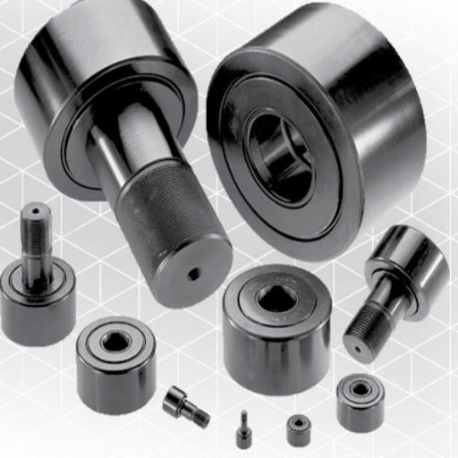
To ensure a cam follower is evident in my head, I will consider its components: the outer race, the needle or the cylindrical rollers, the inner race, and the shaft or stud. The first one is the part that interacts with the cam or track, and it is frequently heat-treated to endure a lot of wear and tear. Internally, there are needle-shaped or cylindrical rollers that decrease friction and allow for smooth movement; these rollers are housed by the inner race that provides the necessary strength for structural support.
At a technical level, I, however, make sure to look into and validate the following critical aspects:
Outer diameter – Determines the area of contact with the cam or track, which is a necessary factor for load transfer.
Roller diameter and number – Determines the load and smoothness of movement; more rollers typically allow greater load force to spread over the same moving object.
Radial load capacity – Determined by the type of materials used, the construction characteristics of the cam follower, and its ability to perform.
Axial play – Should be as small as possible to preserve the degree of alignment and performance, but in general, tri-micrometric cumulatively choking on the application.
Material hardness: The outer race and the rollers should have a relatively high hardness (generally HRC 58-65 range) to withstand the wear with use over time.
Considering all these structural components and technical details, I can assess the problems that might arise while operating the cam follower under various situations and assure myself that it will function properly.
Importance of Regular Lubrication
Lubricant must be regularly applied for the proper operation of a cam follower and its integrity and longevity. Adequate lubrication reduces friction and dynamic and static loads, lowers the working temperature, and externally attaches contaminations and corrosion, complicating a component’s performance. Hence, I ensure the device’s lubricant conforms to the following parameters for effectiveness.
Ecological temperature: The infusion must be stable over a range of temperatures, usually between -20°C and 120°C, depending on the application.
Viscosity Should align with the standard operating velocity and load; for example, viscous fluid should apply lubrication where the speed and load are medium.
Base oils and their mixtures: Lubricants containing anti-wear and EP (extreme pressure) additives for a high load should be avoided as they prevent surface wear during the application.
Concerning all the above technical parameters, I managed to keep the cam follower working in good condition and with smart design integrity and strength.
Identifying Wear and Tear in Roller Bearings
As I work on roller bearings and their wear, certain factors are interesting, and I relate them to the relevant technical parameters. For example:
Visual inspection: I look for discoloration, scoring, or surface spalling, which usually accompanies poor lubrication or contamination. The lubricant film thickness (oil viscosity) must be sufficient for the operating speed and load.
Noise and vibration: If a machine has misalignment or excessive wear or fatigue, it becomes noisy or vibrates more than it should. I employ vibration analysis, setting aside the RPM and bearing clearance to detect abnormalities.
Operating temperature: friction or bearing material wearing can indicate a temperature rise. The recommended operating range of -20°C to 120°C reduces the thermal stress of components.
Lubrication condition: I am keen on the appearance of oxidation, contamination, and depletion of additives like anti-wear or EP in lubricants. Regular monitoring ensures that the oil constantly maintains its protective ability.
Carrying out these technical measures systematically, I can pinpoint and obliterate wear on the bearings and prolong their working life with functionality assurance.
What Are the Benefits of Shopping by Brand for Cam Followers?
Exploring Reputable Manufacturers
As I look for an optimized and best-quality Cam follower at the manufacturers, I look for their experience, quality, durability, and innovation. Going with a trusted brand is ideal for avoiding issues of consistent performance and timely service life of such applications. I make sure I consider the technical parameters that serve as a justification for my choices as follows. As follows.
Material quality: The manufacturer’s use of high-grade alloys of specialty materials for strength against wear to ensure perpetual reliability is one of the significant factors that I consider.
Load capacity: Equally crucial to ensure that the machinery functions appropriately, I verify the cam followers’ dynamic and static ratings to ensure my machinery can operate in its required conditions.
Surface finishes: For manufacturers, often heat treatment coats or other ways that are advanced in nature for reduction of friction are the common surfaces developed
Precision engineering: I verify with the manufacturer whether a component can be made of narrow or broader tolerances, as this would affect how smoothly the system will perform.
Manufacturing standards: Whether the processes are ISO compliant or not is a sure sign that there is quality assurance and that many standards are met.
Focusing on the Cam followers from the manufacturers above enables me to quickly match my technical requirements and operating specifications, which is always guaranteed from the manufacturer’s perspective.
Comparing High Load Capabilities
When it comes to the cam followers’ advanced load capabilities, there are several key parameters I bear in mind so that planning cam followers go in the right direction in terms of the requirements:
Load Capacity: My review of the specifications includes an analysis of the dynamic and static load ratings, so if I plan on using a cam follower with a higher dynamic load, it would mean that the cam follower would be subjected to, possibly, continuous stress, as for the static load, it dissects stationary type loads that could be enforced without deformation to occur.
Material Strength: The cam followers made from high-grade alloy steel possess unique properties as they can withstand large amounts of tensile strength.
Bearing Design: full complement needle rollers or heavy-duty ball bearings are a solution and a necessity. These designs redistribute loads across the follower, thereby lessening the stress concentration and improving reliability under heavy loads.
Lubrication System: In advanced conditions, grooves are present or seals are used, this reduces friction thanks on maintaining performance under high load conditions.
Axial Load Support: The cams incorporate axial load support features such as rim flanges for applications involving side forces.
Considering the factors above relate to my system’s requirements, I can conclude that the cam follower I select can withstand high loads and function without any side effects.
Selecting Heavy-Duty Models for Specific Applications
While focusing on heavy-duty cam followers, I go through the factors mentioned and assess them as follows.
Material Strength: I make it a point to establish that cam followers use hardening metal, such as hardened steel, to enhance their survivability amidst high and continuous loads. This guarantees that it is fit for challenging operating situations.
Load Capacity: I ensure the load limits satisfy the application’s dynamic and static load capacity requirements. For instance, the dynamic load can be rated at 10,000 N, while the static load will be rated at 15,000 N.
Operating Temperature Range: I check the expected working temperatures from -30°C to 120°C, ensuring that the component can efficiently perform at those temperatures.
Lubrication System: I assume automatic grease fittings are required to shorten maintenance periods and allow the part to function appropriately under load.
Axial Load Support: If the application has lateral forces, such as side forces connecting it, I determine whether the cam follower has flange rings or any other device to control axial loads. If the system needs such a function, it enables handling axial loads of around 2000 N.
After going through each of the parameters set and addressing them, I have no doubt a heavy-duty cam follower that fits all of the application’s needs will be selected.
Why Should You Shop by Category for Track Roller Bearings?
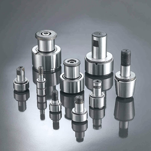
Understanding Different Types of Roller Bearings
In short, the application requirements and the technical parameters of the model can be considered when choosing an adequate type of roller bearing. Here’s how I do it: Generally, I start with a combination of Ultimate Overload Frequency and Internal Clearance.
Cylindrical Roller Bearings: These self-lubricating bearings are mainly suitable for heavy radial loads and modest speed. When very high radial stiffness is required, I choose them to ensure that the load rating is adequate or more than what the system can deliver. In the case of industrial machinery, an up rating of 200 kN is usually sufficient.
Spherical Roller Bearings: Dealing with shaft deflection or misalignment, I use spherical roller bearings as they are self-aligning. For those cases, I confirm their dynamic load rating that usually. This could be the standard range of 100-800kN, depending on applications.
Needle Roller Bearings: These bearings have a compact structure, so their dimensions and mass can be reduced. They have a high load capacity with their dimensions. I ensure that such bearings are alright with the restraint maxim beam loads of 15 kN-30 kN in a limited space constructed.
Tapered Roller Bearings are required in applications where radial and axial loads must be supported simultaneously. Such bearings are required in couplings and wheel hubs, where the axial load could be as much as 50% of the radial.
Thrust Roller Bearings: I prefer thrust roller bearings when the vertical load is the main force, such as in vertical shafting systems. Their axial load capacity, which is quite commonly within the range of 20 kN to 500 kN, is the one consideration I make sure matches the operational speed and required support.
So if I can analyze these parameters and correlate them to the required conditions of the application, I can be sure of the best roller bearing type to work most effectively and reliably.
Choosing Between Stud Type and Yoke Type Cam Followers
When choosing between stud-type and yoke-type cam followers, I will compare their specifications with the application’s specific requirements. In the case of stud-type cam followers, it is clear that they have an integrated stud, which makes mounting the cam follower onto the supporting structure quite clear to me. They are best suited for apolitical scenarios which do not consider high amounts of radial loads to a priority. In most cases, the radial loads performed on the stud-type cam followers range between 8 kN and around 8 kN, depending on the configuration and size where I have worked on them primarily.
I prefer Yoke-type cam followers when radial loads are heavier at more radial loads than that stud type. Its design allows this to be fitted on the shaft or pin, ensuring better load-bearing and stability. These can withstand radial loads of about 15-20 kN or more, making them practical for application in an industrial setting. Additionally, yoke-type cam followers are advantageous in environments with misalignment issues due to increased radial loads, as they have a greater contact area with the raceway, which allows them to withstand such conditions.
I can analyze and compare the weight load, test subject settings, and conditions of each type and, depending on that, make a well-informed decision that would increase the performance and the reliability of the designed model.
The Role of Crowned Outer Rings in Load Distribution
Crowned outer rings are essential in improving load-carrying capacity and edge stresses and allowing for smooth operation under different load configurations. I consider them to be quite helpful, especially in circumstances where applications may have misalignments or deflections. The outer ring’s crowned shape enables it to cope with very slight angles, making the chances of minimal high-stress points and ultimately increasing the component’s life.
In terms of key technical parameters, some geometric factors need to be considered to select crowned outer rings:
Contact Pressure: The profile geometry of the crowned section reduces the contact pressure at the peripheral edges compared to outer rings, which are flat and, therefore, assist in contact uniform distribution across the surface area.
Maximum Load Capacity: For the crowned outer rings, industrial applications with radial loads equal to or greater than 20 kN find the crowned rings helpful, as they reduce the deformation of the element exposed to the load.
Misalignment Tolerance: These crowned outer rings correct for the initial angular misalignment of the rings of about 2 to 3 degrees to function efficiently in rotating machinery.
Durability Under High-Stress Conditions: These outer rings deform less than flat rings in repeated cycles of loads, making them effective in applications where load variations are relatively frequent.
Implementing these parameters allows me to assert and substantiate my choice of crowned outer rings in circumstances requiring increased precision, stability, and durability. Crowned outer rings can solve operational problems and play an essential role in performance optimization and service life enhancement.
What Are Common Installation Challenges for Cam Followers?
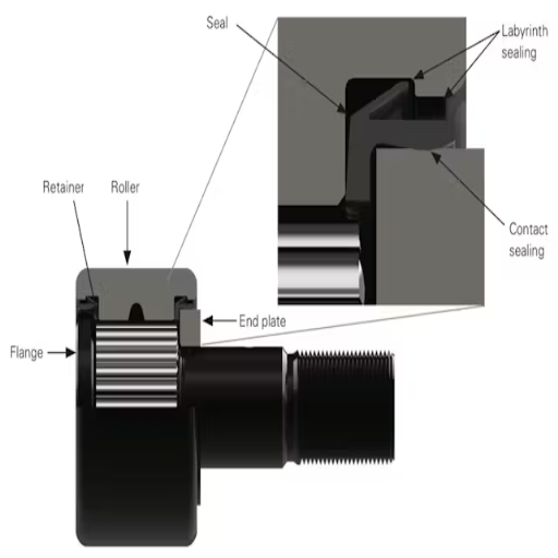
Addressing Misalignment Issues
Cam followers are usually installed with misalignment issues; understanding the underlying mechanics is crucial to correct them. I have learned from experience that such factors are important to ensure that the bearing surface is less likely to be subjected to undue stress, which can cause it to wear out or cease to function well within a short time. I make sure that the following steps are taken in this regard:
Assessment of Parallelism: The follower and its mounting surface should be tested for parallelism. Any distance beyond 0.02 mm would jeopardize performance and load distribution.
Correct Shaft Fit: The cam follower shaft, to avoid excessive horizontal movement, should be seated in its place adequately, preferably within H7/h6.
Lubrication Considerations: I always ensure the lubrication pathway is correctly positioned to absorb misalignment and remain open. I prefer greases with thick viscosity for equipment that would be used under significant misalignment recipes, say 0.5-1 degree.
Load Distribution Analysis: Many times the cause of uneven load bearing is misalignment, in such events, I make use of these and ensure that operational parameters had load within normal limits, for example 70% of maximum rated dynamic load capacity.
Applying these parameters with high accuracy when carrying out the installation procedures allows me to solve the misalignment problem, thus significantly extending the cam follower’s operational life and improving the system’s overall functioning.
Proper Mounting Techniques
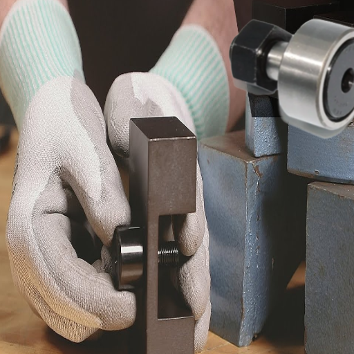
When integrating diverse mechanical structures, I tend to adopt a specific order in my work process as it relates directly to the functioning of the cam follower components. As a first step, I check the alignment of the mating surface with the help of appropriate tools, like dial gauges or laser aligners, ensuring that if any misalignment occurs, it is within the limits set by the manufacturer. This stage is essential since it minimizes the load on the cam follower and the chances of wear out.
Other than that, I aim to follow the torque application during the fastening process to ensure it is worth the recommendation. Most of the time, I look at the manufacturer’s torque recommendations, and it seems the values are determined by the size or material of the fastener—for instance, steel constructions M8 bolts 25-30 Nm. Adequate torque prevents loosening and makes placing the cam follower in the correct position easier without changing its shape.
I often need shims or spacers to obtain the exact correct positioning, for example, due to extreme tolerance. These elements help maintain appropriate clearance and alignment in many instances. I also ensure that the lubrication ports line up with the mounting surfaces to ease the structure’s regular servicing.
Respecting all these steps punctually and the technical regulations sensibly reduces the probability of installation errors and provides adequate conditions for the system’s reliability and efficiency.
Using Eccentric Stud Cam Followers for Adjustability
Eccentric stud cam followers are very convenient for systems that require them to be adjustable. They enable accurate and close alignment without complementing installation components. I use them to adjust the contact or preload in systems where almost perfect alignment is essential. Turning the eccentric stud allows me to change the cam follower’s position about its surface plate, thus altering its interlocking with another engaged part.
Eccentricity Range: The eccentricity reasonable for most alignments is within 0.4mm to 2mm, targeting an angle of duct rotation not exceeding 30 degrees.
Torque Specifications: The stud should be tightened to the M8 bolts (for steel connections) to a torque of 25 -30 Nm so that it does not turn during loading.
Material Compatibility: The cam follower may be made of stainless steel to use against corrosion and minimize rusting-out effects.
Load Capacity: I check the dynamic and static load ratings to ensure they do not exceed the system’s rating while utilizing the component to prevent damage.
The eccentric study focuses on these parameters. Precious adjustments help improve the system’s performance and longevity as the chances of misalignment decrease.
How to Enhance Corrosion Resistance in Roller Bearings?
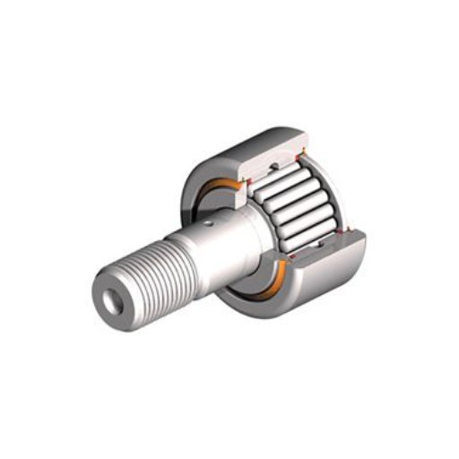
Material Selection for Outer Ring Durability
In designing the outer ring, I focus more on corrosion-resistant material selection, choosing materials that provide good wear resistance and suitable conditions. We primarily use stainless steels like AISI 440C or AISI 304 for anti-corrosive applications because they resist oxidation and moisture penetration. Moreover, ceramic-coated or martensitic stainless steel is also helpful in some cases of high strength and anti-corrosive property requirements.
Corrosion Resistance: To avoid rusting and pitting, confirm the corrosion resistance control measures according to the American Society for Testing and Materials (ASTM) A380 standard for stainless steel.
Hardness: Confirm that AISI 440C Stainless Steel Grades, which withstands wear, achieves a hardness of Rockwell C scale (HRC) 58 to 65.
Temperature Resistance: For high-performance use, select those materials that can operate at a temperature of 250´C or more.
Load Capacity: Provide minimum tensile strength, e.g., for AISI 440C 190 to 200 ksi, while engaging temperature for applications to avoid its deformation under stress.
Considering the above parameters appropriately, I can ensure that the roller bearing environment is created so that the outer ring is highly corrosion-resistant and able to withstand wear.
Applying Protective Coatings for Enhanced Longevity
The protective coatings are applied to prolong service life, but I ensure they are chosen based on their operational requirements and align with the abovementioned technical parameters. As an example,
Corrosion Resistance: I select PVD or CVD coatings to best protect against size alteration through rusting or oxidation and ensure that the material satisfies USA ASTM A380 or its equivalents.
Hardness: For components where wear resistance is required, I check that the coating has assisted in achieving a surface hardness within Rockwell 58-65 HRC, such as stainless steel AISI 440C.
Temperature Resistance: I apply ceramic or DLC, which can be used at temperatures of 250°C and above.
Load Capacity: The selected coating should not reduce the tensile load strength requirement of the substrate material to a value less than 190-200 ksi.
It has, therefore, been possible, through consideration of required parameters and their justification, to select and apply protective coatings that will extend the life span and increase the efficiency of the components.
Maintaining Lubrication to Prevent Corrosion
I use good quality lubricants suitable for the coating, materials, and working conditions to keep metal parts from being corroded and deprived of oil. For example, I incorporate lubricants that contain anti-corrosive additives and are compatible with coatings such as PVD, CVD, or DLC are used. There are particular technical parameters and explanations that I take into account:
Viscosity: For lubricants, I look at the appropriate viscosity index about the temperatures at which they are used (for instance, ISO VG 32-68 would work for moderately low temperatures) to cater to optimum film thickness and wear protection.
Thermal Stability: With high-temperature coatings, the lubricant is said to be thermally stable as long as the temperature is below 250 degrees celsius without breaking down or carbonizing itself.
Water Resistance: I use rust-inhibiting oils or synthetic greases, and I ensure that the lubricants I employ have a high degree of water repellency so that water does not seep in and start rusting.
Adhesion Properties: I opt for lubricants with high adhesion to the surfaces so that exposure to wet or moving conditions doesn’t cause lubricant washout.
By sticking to the above parameters, I ensure that the oil not only acts as a lubricant, thereby avoiding friction but also actively prevents the material from coming into contact with environmental factors promoting oxidization, increasing the life and performance of the parts.
Frequently Asked Questions (FAQs)
Q: What steps can be taken to ensure cam follower rollers have a longer service life?
A: Cam follower rollers may require proper alignment, preventive maintenance, and tools to aid in lubrication. Wiping the components with a cloth to get rid of dirt and oiling the parts will be a good idea to attain that equilibrium.
Q: At what intervals should cam followers be lubricated to facilitate consistency?
A: When it comes to cam followers, lubrication can be tailored to suit how they are being used. Following the manufacturers’ instructions is recommended before finalizing whether more lubrication is necessary or just regular lubrication will suffice.
Q: What should I do if a cam follower that has stopped functioning needs to be replaced?
A: If a cam follower is beginning to make excessive noise or vibration or has a high level of play in the component attached to the follower’s shoulder, then it is most likely damaged. Furthermore, inspecting the cylindrical outer ring or the needle bearing for any signs of wear or tear will aid in determining when to replace any cam followers.
Q: What is the installed hexagon socket on a stud-type cam follower used for?
A: Cam followers that have a stud type in its design is fastened to a hexagon socket which facilitates straight locking, this also makes it easier to interchange between one cam follower to the other if the need arises.
Q: Can eccentric cam followers be used in cases that involve non-constant loads and forces?
A: Yes, bearing eccentric cam followers can attach themselves to a cam or track placed onto them, allowing these devices to be used in cases with variable radial and axial loads placed on them as per the requirement of the application.
Q: What problems may not allow perfect flange maintenance on cam followers?
A: The primary function of the flange is to axially retain the cam follower so that it remains adequately oriented along the intended axis. Rotational flange wear resists rotational movement, so if trimmed, it can help cast stability and performance under radial loads.
Q: Why is the cam follower roller’s component cylindrical outer ring of relevance to the subject in discussion?
A: The outer ring of significant relevance to the subject in discussion is cylindrical; as such, it allows the needle roller bearings to mount onto it preceding rotation, thereby minimizing friction, wear & tear. Effort must be taken to ensure that this part is not damaged as it i crucial for the cam follower.
Q: How does the maintenance of yoke-style cam followers vary from those of other cam followers?
A: Yoke style can generally lead to some deformation, resulting in misalignment of the yoke for the cam track and further complicating yoke assembly maintenance. Also, look for failing needle bearings and lubricate them regularly so they don’t do so again.
Q: How do axial and radial loads influence the maintenance of cam followers?
A: Cam follower maintenance is better done when a technician is aware of the nature of loads acting on the cam follower. Radial loads alter the inner ring and needle bearings, whereas axial loads influence the flange and general placement.
UCTH213-40J-300 with Setscrew(inch)
CNSORDERNO: Normal-duty(2)
TOGN: UCTH213-40J-300
SDI: B-R1/8
SD: 2 1/2
UCTH212-39J-300 with Setscrew(inch)
CNSORDERNO: Normal-duty(2)
TOGN: UCTH212-39J-300
SDI: B-R1/8
SD: 2 7/16
UCTH212-38J-300 with Setscrew(inch)
CNSORDERNO: Normal-duty(2)
TOGN: UCTH212-38J-300
SDI: B-R1/8
SD: 2 3/8
UCTH212-36J-300 with Setscrew(inch)
CNSORDERNO: Normal-duty(2)
TOGN: UCTH212-36J-300
SDI: B-R1/8
SD: 2 1/4
UCTH211-35J-300 with Setscrew(inch)
CNSORDERNO: Normal-duty(2)
TOGN: UCTH211-35J-300
SDI: B-R1/8
SD: 2 3/16
UCTH211-34J-300 with Setscrew(inch)
CNSORDERNO: Normal-duty(2)
TOGN: UCTH211-34J-300
SDI: B-R1/8
SD: 2 1/8


