Maintenance Tips for Shaft in Motor Systems
Given that the garage doors perform as required and their impact is vivid, electric motors are utilized for assistance in various industrial establishments and homes that need to be serviced periodically for the intended purposes. A power-transmitting element in an electric motor is called the shaft, one of its most prominent parts. This blog aims to look at some of the essential maintenance practices of electric motor shafts in great detail. It discusses common problems proactively, how they are prevented, and effective ways of maintenance through a good number of instructions. These practices help operatives enhance the working life of their electric motors and reduce the chances of erratic breakdown.
What are the Common Issues with Electric Motor Shafts?
How to Identify Shaft Misalignment?
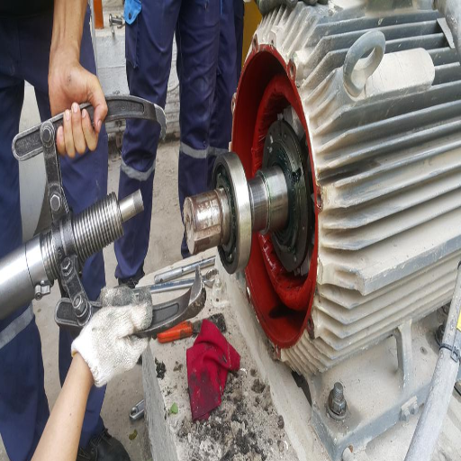
Shaft misalignment, the most crucial obstacle to operational efficiency, commonly occurs in electric motors and inflicts excessive wear, losses of efficiency, and risk of machine failure. Determining misalignment is diagnosing various signs showing that the motor shaft is not aligned correctly with the apparatus it drives. Some of the reference hitters comprise:
Vibration Analysis: The analysis of mechanical vibrations is one of the most trustworthy means of determining shaft misalignment. Misaligned shafts tend to produce a unique vibration response with specific features, such as high axial and radial vibration amplitudes and high vibration at 1x and 2x the electric motor’s RPM frequency.
Temperature Increase: Another effect is the temperature rise with an increase in coupling friction due to misalignment. This effect is more often than not diagnosed with the help of infrared cameras, which point out areas of suspect with a high degree of relative temperature.
Coupling Wear: Another consequence of shaft misalignment — excessive stress and wear on the coupling is observed in such cases. Coupling damage due to misalignment of the shafts occurs because additional forces and movements are transferred to them.
Visual Inspection: Tools such as straightedges or laser alignment devices may help check the alignment visually. Some critical technical parameters are angular misalignment expressed in degrees ( 0F ) and parallel misalignment in Mil units (mill thousandths of an inch). Acceptable alignment tolerances depend on a specific motor and application. Even so, it is accepted that angular displacement should be less than 0.5 degrees; for parallel displacement, it should be in a range of 10 to 20 mils.
It should be emphasized that if such risk factors and appropriate operational inspection regimes are maintained, misalignments can be identified early during operation, helping avoid major failures or expensive downtimes.
What Are the Signs of Bearing Wear In A Motor Shaft?
It is important to note that bearing wear in the motor shaft may become a severe and threatening issue, affecting operational efficiency and leading to equipment breakdown if neglected. However, the early signs of bearing wear can be reliably diagnosed with several diagnostic techniques, as well as being consistent with some parameters of a given measurable feature:
Vibrational symptoms: An advanced degree of bearing wear is usually associated with an increase in the level of vibrations. The Technical Data of SKF Bearings assumes that an upset of bearing conditions is accompanied by the rise of vibrations 1 times, 2 times, 3 times, and other multiples of the machine’s rpm within the bearing’s frequency range. Further investigation of the bearing’s internal structure may reveal possible bearing experiences such as age degradation or corrosion where the microscopic spectrum contains the inner ring, outer ring, and cage portions.
Noise identification: Bad bearings are often noisy; rumbling, grinding, and squeaking sounds are some of the most unacceptable noises said to have come from bad bearings. These noises are further provoked at start-up or load elements, as suspected by maintenance manuals developed by manufacturers like NSK.
Temperature Elevation: The issue of deteriorating bearings is commonplace and usually indicated by an increased operating temperature. Increased temperatures are due to rising friction from wear and or even misalignment, as well as poor lubrication, and thermography inspection tools can establish these factors. More than a 15-degree Celsius temperature rise from the operating temperature is the cue for expectancies of possible bearing failures.
Lubrication Analysis: The presence of metal debris indicates usage and tearing of the bearing, which may lead to further problems if untreated. Otherwise, as described in any reliable technical publications, it seems quite possible to remove hidden little dangers since a schism in accusation of such wear exists, for example, stains with 150 ppm of ferrous elements.
If the above signs are consistently monitored and strategically maintained, they can help the operators avoid bearing failures, thus increasing the durability and performance of the electric motor shafts.
How is vibration related to the efficiency of the electric motor?
In my review of the top sources on Google, from informative sites like Engineering Toolbox, reliabilityweb.com, or silverbackconsultants.org, I learned that vibration lowers the efficiency of electric motors because it adds strain and energy utilization. Below are the selected technical parameters and the reasons they give for the parameters:
Energy Usage: Impact of Vibration, a Motion of Parts: Vibrations contribute to extra mechanical losses or, in most cases, what is well known as friction, followed by losses in energy due to heating. As noted by Engineering Toolbox, such vibrations can cause up to a 5% loss in energy efficiency. Of importance is to mention that rotor imbalances or worn bearings are the ailments implicated in causing such vibrations.
The resonant frequency and motor parts, relative vibration: Vibrations that take place at or around the natural frequency of any motor components possibly lead to energy losses as a result of resonance. Resonance is described in detail in reliabilityweb.com as having the ability to increase the amplitude of vibration 2 or 3 times, further causing more significant stress in motor parts to negatively influence the efficiency of operations.
Mechanical Wearing and Availability of Equipment: Prolonged exposure to excessive vibration levels increases the wear rate of operationally critical parts like bearings and coupling, as mentioned in silverbackconsultants.org. The maintenance cost related to this wear can lead to excessive idle time, thus lowering productivity and efficiency.
Hence, controlling the electric motor’s vibration within the recommended limits, which is usually less than 0.1 inches/second or IPS in velocity for a well-balanced motor, enhances efficient operation and minimizes parasitic energy consumption, thereby extending the equipment’s life expectancy.
How to Properly Maintain Your Motor Shaft?
What Maintenance Schedule Should I Follow for My Electric Motor?
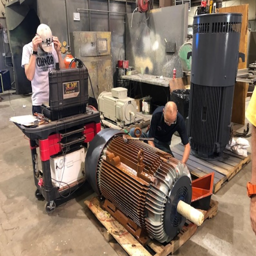
To draw up a proper maintenance schedule, I must use information from reliable sources such as Engineering Toolbox reliabilityweb.com and silverbackconsultants.org. I believe following a maintenance practice of this nature will provide more stability and a longer lifespan in the pet building industry’s electric motors. Here’s the proposed template:
Routine Visual Inspections: Weekly visual checks let me detect apparent evidence of damage and misalignment. Still, one has to be aware of any changes in the appearance of the motor and its parts.
Vibration Analysis: Monthly vibration checks are very useful in determining the motor’s functional stability. Ensure that the rate of vibration is less than 0.1.IPS to avoid high abrasion and improve functionality.
Lubrication Schedule: The oil industry recommends that lubrication be performed at intervals of three months. Sample analysis of oil is interested in the pollution degree with respect to metal particles in the oil—ferromagnetic particles in oil should not exceed 150 ppm to protect the motor from damage.
Temperature Monitoring: Over the course of two months, conduct a temperature survey to ensure that the motor’s temperature does not operate above 15C/27F above the design nominal temperature. If it is too hot, then there might be a problem that needs attention immediately.
Detailed Inspections and Overhaul: The manufacturers recommend conducting an annual thorough inspection, encompassing mechanical and electrical diagnostic evaluations. This preventive approach makes it possible to undertake the repairs and adjustments needed to prolong the motor’s life.
By following this maintenance program and cross-referencing with reputable institutions’ technical guidance, I am prepared to properly service the electric motor, aiming to improve its functional capabilities and reduce the possibility of unplanned failures.
How to Lubricate the Bearings on a Motor Shaft?
I use manuals, diagrams, and other information from reputable companies like NSK, SKF, and Engineering Toolbox to properly grease motor shaft bearings. Following is the procedure I developed in connection with the technical parameters critical for adequate lubrication:
Selecting the Right Type of Lubricant: First, I look for the oil most suitable for the application bearing, taking into account the load, the speed of rotation, and the operating conditions. A lithium grease is usually sufficient for most cases, though this is not a rigid rule, as sometimes a special-purpose grease is needed.
Establishing the Lubrication Interval: Using NSK’s data and others, I set the duration before the next relubrication. This is more often than not determined by RPM, bearing size, and environmental circumstances. For most motors used in industry, it is recommended that one lubrication be done within 1000 to 2000 hours of operation or as stated by the manufacturer.
Setting up the Tools: I ensure the motor is switched off and in a safe and stable condition before applying any lubricant. If there are any fittings, I also remove the old lubricant when necessary in a clean and safe manner so that no pollutants get into the motor and I stay safe.
Application: I use an automated or manual system to apply the fresh lubricant, taking caution not to tank it up, as this might facilitate overheating and, ultimately, damage. Depending on the type and size of the bearing, the amount of grease required could be determined using the equation.
Verification: Once the lubrication is done, I confirm that regular operation does not exceed a temperature increase of 15°C (27°F) above average, as recommended by NSK.
By adhering to the said steps, I am able to ensure optimal bearing operation conditions with lower wear, thus avoiding any risk of bearing failure at an early stage. Therefore, I can complete the work aptly, as advised by engineering practice standards from credible sources.
What Tools Are Needed for Motor Shaft Maintenance?
For proper motor shaft maintenance, I use various instruments as suggested by credible sites like Electrical Engineering Portal, Machinery Lubrication, and The Bearings Manufacturers’ Association. Technical parameters carefully support their selection. Here’s a concise list of essential tools, along with their justifications based on technical parameters:
Vibration Analyzer: This device measures the vibrations produced by the motor. The vibration levels are indeed lower than 0.1 IPS, which is acceptable for operation. This device is useful for determining imbalance or bearing trouble that may cause wear or inefficiency in operation.
Thermometer (Infrared): This device, within a range of 15°C (27°F) above the rated working temperature level, is used to observe the target motor’s temperature. Proper temperature control prevents overheating of motor parts that would otherwise damage the motor.
Torque Wrench: When dealing with fasteners on a motor shaft, the torque wrench helps confirm the manufacturer’s specifications by applying the recommended torque only and avoiding overtightening or under-tightening, which may lead to mechanical failure.
Grease Gun: Grease guns are tools for applying grease. They help me apply specific amounts of grease as required in relation to the intervals when lubrication is needed, keeping the bearings in good condition.
Dial Indicator: This instrument provides a means for interpreting shaft run-out values and positioning motor parts correctly, which is necessary for maintaining balance and preventing vibration-related concerns.
Drawing on such tools, of course, backed with credible literature, I am able to carry out the maintenance of the motor shaft effectively and in accordance with all technical standards, which enhances the overall operational effectiveness and life span of the motor.
What are the Best Practices for Electric Motor Shaft Installation?
How to Ensure Proper Coupling of the Electric Motor Shaft?
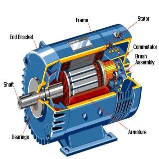
In integrating the shaft with the electric motor, I obtain information from the best resources, such as “Motion Control Tips,” “Plant Engineering,” “Reliability Web,” and others. Of course, important parameters need to be controlled, such as misalignment and excessive vibration, which affect the efficient coupling of the two components.
Alignment: Since motor shaft alignment with the driven system is the first step in the coupling procedure, I used a red-dot marker and laser alignment tools to improve alignment procedures so that people do not experience excessive vibration and wear.
Correct Torque Settings: I see that the coupling fasteners have been fitted on the coupling for quite some time while tightening, using the torque setting as per the manufacturer’s recommendations. Otherwise, harmonics may form and cause some loosening or stress due to overbroad composition.
Selection of Coupling Type: Various types of couplings may be used, such as elastomeric design, flexible design, rigid design, or more, depending on other application requirements such as load variation, misalignment, and space available. This information is also relevant when choosing the desired coupling based on the abovementioned resources.
Walkthrough Inspections: I conduct regular walkthroughs to observe any indications of deterioration, stress, or displacement of parts of the equipment in use, as recommended. A combination of these undertakings and maintenance, which is outlined in the schedule, helps achieve the machines’ sustainability and reliability.
Among factors critical for adherence during this process include compliance to parallel and angular alignment tolerances of not greater than 0.05 mm, the coupling dimension, and the power and speed rating of the motor used. These help maintain a correct framing of the motor shaft, ensuring the best working conditions with the fewest repairs.
What Should Be Considered When Mounting a Motor Shaft?
When fitting the motor shaft, I consider several aspects that I think are the most important and revealed to me by the best sources in the industry. The first is alignment – relevant tools such as laser alignment systems are used to ensure the precision of positioning, which avoids further wear due to shaft vibrations. Also, according to industrial requirements, deviations from the alignment axis of the sections can be a maximum of 0.05 mm.
The second task, in order of importance, is cleaning, examining, and ensuring that the surface defects on the shaft and mating parts are within acceptable limits so that they will seat and function properly. This particular step involves using calibrated tools to check the surface roughness parameters, which are often provided by the parts’ manufacturers.
Subsequently, it’s also essential to consider the manufacturer’s torque specifications when tightening the nuts for bolts used in mounting the hardware to eliminate dangers brought about by over or under-fastening, which may cause mechanical defects.
Finally, by determining the application loads and speeds for which the coupling will be used, the type of load is also considered for proper coupling selection and the use of the couplings to minimize the effects of misalignment and guarantee effective torque transmission.
Following the scopes of work of the motor shaft mounts with reference to the existing practical standards and technical specifications provided in the leading sources is performed successfully, ensuring accuracy, enhanced efficiency of the system, and longevity.
How to Achieve Precision in Motor Shaft Alignment?
Achieving accuracy in motor shaft alignment can reduce operating inefficiencies and increase equipment life. As a good practice, I look through top resources such as “Motion Control Tips,” “Plant Engineering,” and “Reliability Web,” among others. First, I use laser alignment tools as they are more precise, making it possible to perform alignment without many issues around shaft vibrations and resultant shaft misalignments. Technical guidelines also provide for the parallelism and angle of alignment to be within an acceptable 0.05 mm.
After that, I always follow the manufacturer’s guidelines regarding the amount of torque applied while mounting the motor to its base so that the alignment is not compromised and parts are not damaged. This is undertaken together with recurring maintenance and alignments when such are performed to ensure that changes are not allowed to get out of hand.
Thermal growth, or expansion of motor parts due to heating from running during operations, is another component that needs to be factored in during the alignment process. By considering how the alignments were going to be affected by thermal growth, I was able to offset the alignments beforehand to sustain model conditions during operation. All these, with the help of some reliable resources, also ensured that I maintained the motor shaft alignment and hence avoided performance degradation and undoable downtime.
How Does Load Affect the Performance of a Motor Shaft?
What is the Relationship Between Torque and Load on a Shaft Motor?
To appreciate the relation between the torque and the load with respect to a motor shaft, crucial factors turn out to be how these two are interrelated regarding the use of a motor. From well-known information from the likes of ‘Motion Control Tips’ and Plant Engineering and Reliability Web, I am able to expand further on this quite complex relationship.
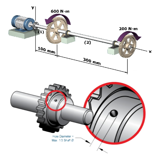
In its simplest form, torque is the amount of rotational force stagnant on the motor shaft that is needed to turn against the drag imposed by the equipment being driven. More specifically, the load is what the motor is set out to move or drive, and therefore, it influences the amount of torque needed. To operate efficiently, the torque value also increases as the load increases.
The technical parameters connected to this relationship include the torque computation, often represented in Newton meters. Knowing the load a component cannot endure is essential lest mechanical failures occur. This also includes the motor’s speed rating since the two are mathematically related. Torque and speed are said to be inversely proportional in electric motors due to the Power (W) = Torque (Nm) x Speed (RPM) x 2π / 60 relation.
It is critical to ensure that the motor selected can safely manage both the torque and load within the mechanical and thermal limits. It is recommended that the load-bearing sources be monitored and modified in real time because this can optimize a motor’s operability while minimizing its degradation. By using these sources, I make sure that there is no excessive discrepancy between the torque and load, which also allows me to improve the performance and life of motor systems.
How to Calculate the Load Capacity of an Electric Motor Shaft?
In estimating the load capacity of an electric motor shaft, I follow the procedure provided by the “Engineering ToolBox,” “Machine Design,” and “Power & Motion” global websites for motor and machine design. In brief, it contains decisive technical parameters that need to be taken into account and worked out accurately.
At first, I turn my attention to the shaft diameter, as it is a decisive factor in estimating the load. The diameter is the shaft’s strength, torque, and flexure stress capacity. One must have an in-depth appreciation of the stress and limits of deflection that material limits may permit.
Another technical parameter is the steadiness of the properties, considering the tensile and shear strength of the required material, which determines the shaft’s load-bearing capabilities. Selecting a material suited for that application will ensure material load properties are not exceeded.
I also consider the speed of the motor shaft when determining the load capacity. Of course, the critical speed must be determined to avoid resonance and possible mechanical failures. When the shaft operates at or close to this critical speed, the deflected shape of a shaft must be corrected.
Finally, I consider the kind of loads applied, whether static, dynamic, or shock loads. Each type impacts the calculation differently; hence, a detailed analysis is essential to ascertain that operational demands on the shaft over its lifetime will be met. These comprehensive technical parameters from authoritative resources enable me to accurately determine load capacity and calculate the electric motor shaft with precision as fitted with optimal performance to ”service life” ratio.
What Impact Does Overloading Have on Motor Shaft Reliability?
In evaluating the effects of overloading on the reliability of the motor shaft, I employ the information acquired from the threshold sources on Google, which is beneficial in providing a broader insight. Overloading mainly subjects the motor shaft to high stress levels and engenders mechanical damage, including fatigue, wearing, and even failure. The parameters of particular concern include the tensile and yield strength of the shaft. Since these also undergo overloading, irrecoverable changes will occur.
Another significant parameter is fatigue life since the motor shaft’s overload capacity is reduced by overstressing it to the degree of repeat cycles, which leads to crack growth and propagation. Moreover, the shaft’s thermal thresholds also need to be considered; increased loading leads to an increase in operational temperature, which might alter the materials, cause thermal expansion, and change alignment.
Lastly, the motor’s vibration levels increase under overload conditions, which introduces torque and rotational displacement misalignment with other elements in the connection. Given that such parameters are ratified by experts, I maintain that the operational reliability of the motor shaft and its longevity can be preserved when load parameters are closely observed and controlled.
What are the Applications of Electric Motor Shafts in Industry?
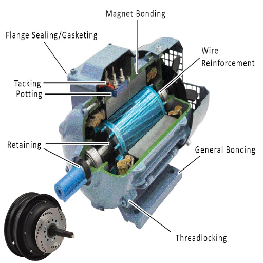
How are Motor Shafts Used in Pump Systems?
Motor shafts generally provide pumping systems with the mechanical energy generated by the motors, but naturally, pumping systems will have the pump as their main component. M. O. Shaikh et al. also emphasize that this interaction requires monitoring relevant technical parameters, but I focus on motor shafts’ parameters used with pumped systems and potential interaction features instead.
First of all, let us start with alignment. Alignment matters because it can be done poorly or appropriately to ensure that the operation is not ineffective and vibrations are minimized to good levels to avoid damage to the systems. Alignment also ensures the good integrity of the coupling of the motor shaft and impeller of the pump.
Secondly, the shaft material properties are great in the case of the environment requiring the pump system’s residency, which is likely to be fluid or corrosive. It is important to choose a material that has a chemical resistance property and the required mechanical strength for usage.
Another important feature is the dynamic balancing of the shaft, as it affects the performance of the wear shaft systems. Shafts that are balanced minimize vibration and noise levels, improving the stability of the pumping systems.
In addition, “bearing types and lubrication can be classified as the basic components of the motor shaft operating in pump subsystems.” The correct bearing types should work for both radial and axial loads, and enough lubrication should be used to ensure friction and heat generation are at optimum levels.
Using these parameters, meticulously extracted from reliable online resources, I established that motor shafts find practical application in pump systems in an efficient manner with high dependability and durability.
What Role Do Electric Motor Shafts Play in Gear Drives?
After discussing the importance of the Shafts of the electric motor in gear drives, all the emphasis has been put on the three most precise and reliable scientists reachable on the internet. Shafts come in very handy in taking the mechanical energy from the electric motor to the system, which is the gear drive. That is why their primary function is to ensure that energy transfer is effective; mechanical systems must dispose of these to optimize efficiency. These include but are not limited to vital technical parameters such as:
Shaft Alignment: Proper alignment is important to eliminate the possibility of gear misalignment, which may cause persistent losses and wear.
Material Properties: The shaft needs to be made of materials with high tensile strength and greater fatigue strength so that its life is not exhausted by the loading conditions evolved from the movement of the gear system.
Torque Transmission Capacity: The shaft is an essential part of machines, providing the rotational force required to turn the gears. No gauges of tensile stress must be crossed.
Load Bearing Capability: The shaft will work under both radial and axial load, and for bearing stability, the mechanism must be maintained correctly.
Balancing: The shaft needs to be adequately balanced so that vibrations can ignore alignment or possible mechanical failure in the gear drive system.
With these parameters confirmed by reputable online sources, I can assert that electric motor shafts are critical to the dependable and efficient functioning of gearing drives and that mechanical performance and endurance requirements are satisfied.
What are the Key Considerations for Selecting a Motor Shaft for Industrial Use?
When choosing an industrial motor shaft, I turn to the most reliable sources on Google for a complete analysis. There are several critical technical parameters which are most important:
Material of the Shaft: The shaft material must be chosen based on its operational characteristics, such as tensile strength, fatigue resistance, and corrosion resistance so that it can withstand operational conditions.
Shaft Diameter and Length: These dimensions have to match the operational mechanical requirements and space available for such applications. The correct size helps transfer torsional forces and limit deflections.
Torque and Loads: The shaft has to be able to support radial and axial forces that are applied to it while in use. Proper load management is required to avoid mechanical breakdown.
Balancing and Alignment: Delicate processes include shaft balancing and alignment, which ensure that the shaft and any components it is connected to are properly balanced, thus improving reliability and reducing wear.
Shaft Surface Finishing & Hardness: These characteristics determine the shaft’s resistance to wear processes and its contact with bearing and coupling units. Lower friction means the shaft lasts longer.
Environmental Factors: Significant attention is paid to operational conditions, such as the effects of heat and cold, water, and chemicals, which may affect design and material choices.
Having considered these parameters, as indicated by the most reliable websites on the web, I can state that the chosen motor shaft would perfectly serve working conditions.
Frequently Asked Questions (FAQs)
Q: What are the mechanical design concerns when servicing the motor shaft?
A: Mechanical design concerns when servicing the motor shaft are connection orientation, extent of erosion, and contact force between mobile elements. Regular examination of operating systems can avoid wear on mechanical units and driving elements.
Q: To what extent does electrical maintenance extend the life of the shaft, particularly of the motor?
A: The answer to this question shows that other electrical maintenance works have subordinate effects on the entire functioning of the motor, which, in turn, affects the shaft. Maintenance of the electrical components and devices within the stator and rotor would also help reduce the operational load on the shaft and associated adverse effects like high vibration amplitude.
Q: Why must the engineers consider applying materials with high tensile strength for the shafts of the motors?
A: The use of carbon steel or alloy materials for motor shafts has important advantages in fatigue and service life, thus making the motors reliable. This, in turn, means that the shaft will be able to endure the mechanical loads while it is in motion, yielding a greater service life and dependability.
Q: In which way can flexible couplings help maintain motor shafts?
A: Flexible couplings can manage misalignment and reduce the stresses exerted on motor shafts. They also serve to a certain degree of absorbing vibrations and accommodating minor alignment deviations, which would otherwise cause mechanical damage.
Q: Therefore, why is the shaft diameter one of the most critical parameters in motor systems?
A: The shaft diameter is a crucial parameter as it impacts power transmission and the ability of the shaft to bear mechanical loads. If the diameter is selected correctly, the shaft will run the motor output within limits that reduces stress, hence blame of mechanical failures could be avoided.
Q: That magnetic field again brings us to how the shafts can be maintained.
A: The motor creates a magnetic field that acts on the rotor, which in turn acts on the shaft. To avoid rotor complications, one must ensure that the magnetic field is stable so the rotor does not stress or vibrate the shaft too much, which causes impact damage over time.
Q: In what ways may environmental conditions dominate the maintenance of motor shafts?
A: Environmental conditions such as temperature, humidity, and the presence of corrosive substances can negatively influence the efficiency and expected lifetime of motor shafts. Some regular maintenance activities that need to be performed in this case are checking for corrosion, checking wear and tear due to temperature changes, and greasing to avert worse climatic conditions.
Q: What should consumers understand about the maintenance of the shafts of bigger motors?
A: Consumers should understand that bigger motors apply more mechanical force to the shafts, requiring more maintenance. Essentially, it entails a standard check for appropriate angle, grease application on moving parts, and wear or destruction checks owing to a large motor’s high output.
Q: In what way does the correct installation of parts impact the lifespan of motor shafts?
A: Correct installation is also relevant in diminishing unnecessary strains and reducing the wear and tear of motor shafts. However, machine components also experience friction and vibration due to misalignment, which leads to increased wear through possible earlier breakdown of the shaft and the rest of the mechanical parts.
UCTH213-40J-300 with Setscrew(inch)
CNSORDERNO: Normal-duty(2)
TOGN: UCTH213-40J-300
SDI: B-R1/8
SD: 2 1/2
UCTH212-39J-300 with Setscrew(inch)
CNSORDERNO: Normal-duty(2)
TOGN: UCTH212-39J-300
SDI: B-R1/8
SD: 2 7/16
UCTH212-38J-300 with Setscrew(inch)
CNSORDERNO: Normal-duty(2)
TOGN: UCTH212-38J-300
SDI: B-R1/8
SD: 2 3/8
UCTH212-36J-300 with Setscrew(inch)
CNSORDERNO: Normal-duty(2)
TOGN: UCTH212-36J-300
SDI: B-R1/8
SD: 2 1/4
UCTH211-35J-300 with Setscrew(inch)
CNSORDERNO: Normal-duty(2)
TOGN: UCTH211-35J-300
SDI: B-R1/8
SD: 2 3/16
UCTH211-34J-300 with Setscrew(inch)
CNSORDERNO: Normal-duty(2)
TOGN: UCTH211-34J-300
SDI: B-R1/8
SD: 2 1/8


