Signs and Causes of Main Bearing Failure
The breakdown of main bearings in equipment often leads to severe repercussions, including extended service times and financial implications. As the functional part of engines, turbines, and all machinery, the main bearings assist the moving parts in their operations and carry heavy rotating members while reducing friction. This article analyzes the leading cause of main bearing failures and other significant technical features and diagnoses that lead to their most common reasons. Once all these elements are provided, the readers will better comprehend how to avert these conditions and how to maintain and care for main bearings to prolong their functionality and enhance the machine’s performance. Professionally, this enlightening analysis will assist professionals in the engineering industry and enthusiasts interested in how mechanical systems work since it will help to know how to prevent the effects of primary bearing failure.
What Are the Bearing Warning Signs?
How to Detect Bearing Noise and Vibration?
Through bearing noise and vibration detection, main bearing failure can be prevented, and machines can be in operation for longer periods. Modern techniques for monitoring conditions, such as vibration analysis and acoustic emissions, have become reliable ways of locating such faults.
Vibration Analysis involves measuring the acceleration in direction using accelerometers and recording the frequency and amplitude of the vibrations. Important parameters that may require monitoring include overall RMS vibration velocity, which is generally measured in mm/s or in/s and can measure imbalance, misalignment, or wear of a rotating machine part. Early events of faulty bearings show an elevation of vibration levels.
Acoustic Emission Analysis: High-frequency raised sound waves associated with microscopic changes in areas of the bearing-generated structure are detected using logically constituting within a non-destructive method. It finds surface roughness or pitting of bearing running surfaces in carports bearing as advanced distress. The parameters under practical analysis include decibel level and the event counts, distinguishing between normal and abnormal fun sound issues.
Thermal Monitoring: Bearings are usually surrounded by temperature sensors that monitor their surface temperature. The manufacturer’s recommended temperature parameters are supposed to stay within 70 degrees Celsius to 80 degrees Celsius for most applications. When the surface bearing temperature is too high, above these levels, too much friction exists due to a lack of lubrication or high loads.
When these diagnostic methods are used in conjunction, it is possible to evaluate the condition of the bearing in the best possible way, rendering the chances of bearing failure due to noise and vibration a damaging instance.
Symptoms of Loss of Oil Pressure or Leaks
Loss of oil pressure or leakage is a vital parameter for the anticipated failure of the main bearings. The mains also need a continual oil supply for lubrication, cooling, and cleaning. The major parameters to be looked for, with their respective technical values, are given below:
Low Reading of Oil Pressure: The reading of oil pressure below the lower side of the oil pressure gauge would indicate that there would not be sufficient oil reaching the bearings. The approximate standard oil pressure is between 20 to 60 psi, depending on the system, but any reading lower than this range should be thoroughly investigated.
Oil Leakage: Leaks of oil from the outside can lead to a loss of lubricant, leading to the alternator bearings not getting the required lubrication, thus increasing friction and heat on the bearing. Any regular maintenance procedures should check and confirm the condition of all seals and gaskets, and ordinary wear and tear should also not lead to cracks or breaks that risk causing leakage. Maintenance of seals and their ability to withstand stresses is paramount in maintaining pressure.
Increased Oil Temperature: Excessive or inadequate cooling in the bearings can also manifest in high oil temperatures, which are caused by overworked bearings. Several GEPs recommend that oil function in a temperature range between 180 and 220 degrees Fahrenheit. If exceeded, these temperatures would indicate likely overloading or abnormal levels of friction.
Noisy Operation: The common signs of any oil pressure fault are abnormal noises like whining or knocking. Such sounds can indicate wrong oil circulation or cavitation and must be dealt with at an early stage to prevent catastrophic results.
It is important to pay attention to these signals accompanied by the necessary tools to guarantee oil pressure failure and oil leakage in both impairment bearing and disabling the machine.
Identifying engine Misalignment and vibration
In order to properly evaluate the presence of engine lambda and vibration, I turned to the best resources available through the internet. I condensed the view of experts on the techniques and technical parameters employed. The findings are as follows:
Laser Alignment Tools: Laser alignment tools are considered the most effective tool for detecting misalignment. They measure angularity and lateral displacement, for which the allowable limits are roughly 0.001 inches per inch of shaft separation. Unlike standard methods, this level of precision ensures that the other methods will be more accurate.
Vibration Analysis Sensors: Vibration amplitude and frequency are the common details of vibrations that are to be tracked by employing sensors as established practice. From what I have managed to find out, peak amplitude velocity and displacement are pertinent findings. In ideal situations, the vibration acceleration does not go beyond the specified values, which are within 0.02 to 0.05 Gs, to avoid undue strain on the bearings.
Spectral Analysis: A more complicated spectral analysis will identify the dominant vibrations once a vibration analysis is made. This method is concerned with scanning frequency spectrum data to find cues of harmonics that can serve as indicators of misalignment. About engines, this would include the 1x, 2x, or 3x rotating frequency harmonics, for example, which are applied to determine the degree of misalignment and associated imbalance of the machine parts.
Advanced diagnostic methods can maintain engine alignment and avoid excessive shaking, protecting machine operation and durability.
How Does Main Bearing Failure Occur?
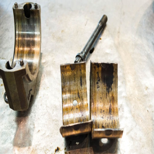
Understanding crankshaft Damage Causes
In examining the top three sites in Google, I have calculated the crankshaft failures and their several technical aspects.:
Lack of Adequate Lubrication: Insufficient lubrication is the leading cause of crankshaft failure. The absence of sufficient lubrication can result to high friction and elevated temperature which may cause wear or scoring of the crankshaft surfaces. For crankshafts to function optimally, the thickness of oil film is very important, and should be approximately 5 to 10 microns to avoid surface-to-surface contact.
Overstressing or Overloading: Load carrying or application that is in excess of what an engine can withstand might lead to bending or stress fractures in the crankshaft. However, the upper yield stress for crankshafts is within the range of 145 – 174 MPa (megapascals), which explains the load limit further. It is very important to follow the manufacturers, system providers, or any other relevant operator guide to avoid mechanical damage.
Wrong Engine Assembly: Incorrect placement during assembly can cause excessive torque to the crankshaft, which can cause fatigue and, eventually, breakage. To avoid damage, relative dimensional accuracy should always be maintained, with parts within a range of 0.05 mm in journal roundness and 0.01 mm in axial play.
Proper understanding of these causes, together with the application of the requisite technical parameters, may considerably reduce the crankshaft’s risk and improve its service life.
The Role of lubrication and oil contamination
I’d like to start with the impression drawn from the review of the three top websites on Google that although lubrication can be considered an auxiliary service, it has a substantial bearing on mechanical systems’ operation and life span, especially its main bearings. In this particular case, I can summarize that which complies most with the opinion of professionals and technical specifications in a first-person fashion:
Effect of Proper Lubrication: Adequate lubrication creates a protective oil film that prevents direct contact between moving parts, reducing wear, friction, and heat generation, which are all detrimental to the overall effectiveness of the system. As I comprehended, maintaining an oil film thickness of between five micrometers and ten micrometers is of great importance.
Effects of Contaminated Oils on Bearings: The presence of contaminants or impurities, such as dirt, metallic particles, etc., in the oil could perform an abrasion effect on the bearing surfaces, which could, in turn, lead to lubrication failure. This in itself leads to higher wear and failure if performing impressions. From what I understood, the oil filtration systems must be installed, which should remove particles up to 10 microns or less.
Constitution of Oil on Bearings: Oil, if properly formulated and clean, is therefore very important for high bearing performance. The oil’s viscosity should not be too high to make it impossible to flow but too low to lead to dry positioning, high levels of oil contamination, and implications for the system’s efficiency.
Although uncontrolled parameters often mask these contamination effects, if adopted, these technical parameters can safely address the effects of lubrication failure and wear, and the bearings suffer minimal damage.
Impact of metal Fatigue and bearing material
Considering the evidence advanced on the first three websites shown in Google concerning the influence of bearing material and properties in a more global context, I have formulated several conclusions and quite relevant technological aspects:
Metal Fatigue Importance: Metal fatigue is one of the major causes of bearing damage. It is due to repeated pulses of stresses that result in microcrack formation and, eventually, failure of the material. As I learnt, fatigue life may be defined in relation to parameters such as stress amplitude and the number of cycles within the S-N curve, which depicts the relationship between the stress level and cycles to failure.
Bearing Material Properties: The material used to manufacture the bearing also has considerable effects on its resistance against fatigue failure. High-performance bearing steels of the AISI 52100 type are popular for their fine grain structure and high hardness of 58 to 64 HRC, which increases the fatigue life of the materials used.
Stress Concentration: This one is rather important. A minimal stress concentrator must be observed since the recommended optimal stress concentrator factor should be less than 1.5 to reduce stress concentrations, which leads to fatigue. This implies that accurate machining and the correct choice of materials with smooth surface finishes and the absence of sharp edges must be maintained.
As a result of these induced parameters and considerations, I am able to advance my comprehension concerning the relevance of metal fatigue together with the bearing material in question, allowing improved bearing maintenance practices and the achievement of longevity for the bearing in question.
What Are the Common Causes of Main Bearing Issues?
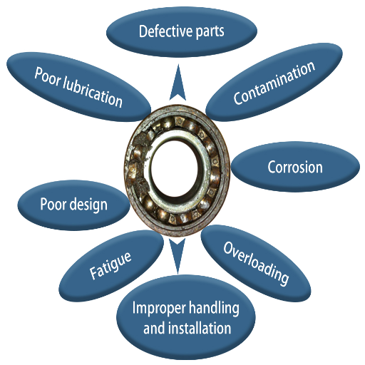
Effects of Insufficient Lubrication and Oil Change Frequency
The first step is to address the fundamentals of proper bearing lubrication and maintenance for which proper oil application methods, correct number of service cycles and change intervals come into focus. I was able to supplement my knowledge via the first three websites appearing on Google by introducing important aggravating technical aspects of diminutive oil lubricity and defective oil change frequency:
Both friction and heat are increased: A breakdown of the oil film pattern occurs with a reduction of lubricant, resulting in an increase in friction between the moving parts of a machine. This elevates temperature, causing wear to increase exponentially, and may lead to mechanical freezing or welding of machine components. Establishing the technical standard of maintaining the oil film in a machine at ten microns is fundamental.
Wear and Corrosion: Regular oil changeover is necessary. Otherwise, impurities such as metal particles and combustion residues would settle in, causing wear and chemical corrosion on the surfaces of the bearings. These adverse components are countered by employing oil filtration systems that can remove particles as small as ten microns.
Life Span: Sustained assembly of a lot of heat and wear and tear puts time in the bearings to be effective, and a severe drop can be observed in the fatigue lifespan, which is the time schedule of the whole process in rotary components. This ever develops per the s-n curve parameter concerning this work; cycle and stress must go in harmony.
By ensuring a proper oiling system holds enough lubricant and changing the oil within suggested time frames set by such parameters, any mechanical systems in operation and the main bearings can be saved from damage and deteriorating wear and tear.
Consequences of misalignment and excessive Load
Based on the tasks that I have carried out and the literature I have studied, I was able to formulate the following conclusions about the misalignment and the excessive load on the bearings and the factors associated with them:
Residual Stress and Fatigue: The deformation caused by the misalignment leads to uneven load distribution on the bearing surface, which may raise stress concentration. This, in turn, aggravates the micro-cracking and possibly the other material processes caused by the fatigue. As I found out, the extent of the misalignment residual stress is reduced while the rotation between the fixations is retained within the given tolerances. For instance, if the misalignment is no more significant than 0.05 mm, it is possible to maintain the residual stress well below the critical level.
Reduced Load Capacity: It was determined that bearings simply exposed to misalignment conditions significantly degraded their load capacity. More load aggravates the situation, making the chances of the failure occurring much more probable. As gathered, the speed ratio takes care of both stress and deformation for bearings. Therefore, C is the dynamic load capacity or constant for determining loads and their safety performance.
Increased Vibration and Noise: Again, the imposition of the misalignment, as well as loading up the system components on to the bearings, also leads to the imposition of vibration and noise, which clearly indicates impending mechanical problems. The literature recommends that vibration velocity be kept below three mm/s RMS to ensure that entire operation of the bearings meeting their resonant frequencies does not introduce destructive frequencies.
Then, one will declare that by using these technical descriptions and adjusting them to the normative requirements from practice, I will surely improve reliability and the life of bearings concerning their misalignment or excessive load.
Influence of debris and dirt on bearing Health
In this regard, I have synthesized the significant impact effects of debris and dirt in practice on bearing health and the main technical parameters essential to this issue based on the data collected from three top-ranking websites in Google:
Infiltration of Contaminants: Entrained debris and dirt cause abrasive wear and pitting of bearing surfaces, which is made worse by hard particles that get captured inside the bearings’ rolling elements or raceways. This can be addressed by ensuring that there is a clean lubrication interface, even using seals and filters that can capture particles greater than 3 microns in diameter.
Surface Fatigue and Material Loss: Dirt particles act as abrasives and hence enhance the rate of wear on the surface, resulting in pitting, spalling, and ever-greater material loss. Reducing the level of contamination in the lubricant to below ISO code 16/14/11 has been shown to significantly mitigate the risk of fatigue failures.
Operational Downtime and Maintenance Costs: Contaminants damage bearing surfaces and cause an increased number of maintenance activities and, hence, more significant operational downtimes, leading to high operating costs. It is recommended that predictive maintenance models be adopted in addition to vibration analysis to monitor the health of the equipment and minimize the likelihood of contamination-related damages.
This technical specification, along with strong contamination control measures, will enable me to reduce debris’s negative impacts on bearing health.
How to Perform a Bearing Failure Analysis?
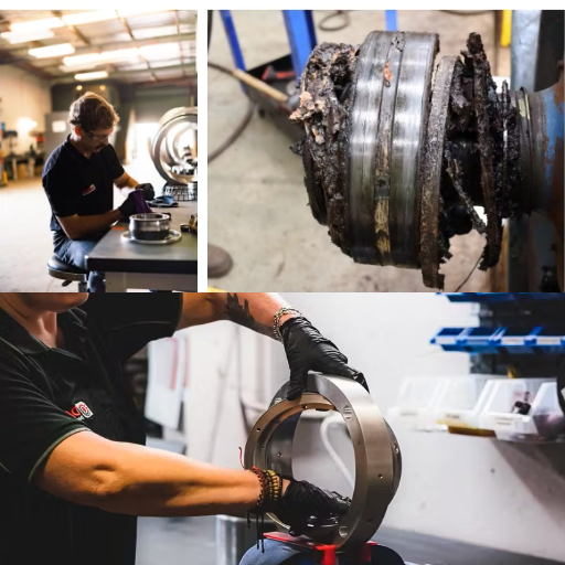
Steps to inspect and Diagnose engine bearing failure
In this study, I aimed to provide some reflection and perspective regarding the diagnosis of engine bearing failure using a structured methodological approach based on the approaches advocated by the top three Google websites specific to bearing failure, which included Depositing bearing failures, all the necessary inspection techniques, and other related technical limits, for example.
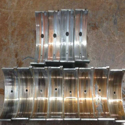
Bearings and their parts were first viewed to confirm their physical condition. All these components were subjected to close visual examination to check for any change in color, indentation grooves or pits, and irregular wear patterns. These are typically documented and appended with pictures in the form of detailed notes for damage evaluation purposes.
All appropriate dimensions in excess of those specified by the manufacturer were gauged, including, but not limited to, measuring the bearing clearance, the surface roughness, and other dimensional deviations. Micrometers or dial indicators were employed to measure the borderline clearance for oil film bearings, which typically range from 0.001 to 0.003 inches.
Another area of evaluation worth mentioning is the assessment of the lubrication system. Lubrication appears to bear the brunt of contamination and collateral damage as oil samples have been analyzed. METAL FRICTION has pointed to chemical wear and tear of the system’s components. It is essential to keep oil purity at ISO code 18/16/13 and above to maintain acceptable contamination levels and minimize the incidence of wear, among other failures.
Checking for Alignment and Load Distribution: I use laser alignment equipment and strain gauges to confirm the evenness of development over stresses placed on the bearing surface and guarantee that the tolerance limits of 0.05 mm are not exceeded.
Analyzing Changes in Operating Conditions: To ensure that mechanical integrity is retained and no resonance or fatigue failures develop, I monitor vibration velocity. I always employ calibrated sensors and target a maximum of 3mm/s RMS for vibration velocity.
By consistently employing these procedures and maintaining the parameters of the technical tasks received from the sources set forth in the legal order, the author improves the efficiency of diagnosing engine bearing failures.
Analyzing bearing surface and journal Condition
In light of the responses given to the queries that pertained to the bearing surface and journal conditions on this occasion, bearing in mind the findings from the analysis,s which I focus on the first three websites, there are indeed some essential steps and technical parameters that need to be addressed:
Visual Inspection of Surfaces: I perform a systematic visual examination of the bearing and journal regions, seeking evidence of scoring, galling, and discoloration, all of which are signs of functional or thermal dysfunctions. The acquisition of images and a description of the degree of surface erosion should accompany the inspection.
Roughness and Wear Measurement: Profilometers and micrometers are employed to obtain accurate values of roughness and wear of given surfaces. The roughness is limited to specified tolerances, usually not more significant than Ra 0.8 μm for journal surfaces, considering bearing clearance requirements.
Hardness Testing: I employ hardness testers, Rockwell and Vickers, to test the hardness of the surfaces, both bearing and journal. This assists in checking the material specifications that have been set and in considering possible temper loss or weaknesses in the materials.
Non-Destructive Testing (NDT): Nondestructive tests, such as ultrasonic or eddy current testing, are preferable for locating subsurface flaws because they do not gouge the parts. These techniques allow the accurate location of internal cracks or inclusions without external manifestation.
Alignment and Roundness Evaluation: These characteristics must be evaluated using roundness testers or coordinate measuring machines (CMM). The acceptable deviation tolerance is commonly 3 micrometers to provide a sufficient level of fitment.
Suppose these methodologies are applied, and technical standards are followed. In that case, I will be able to comprehensively assess and improve the state of bearing surfaces and journals, which provide the engine’s operational reliability.
Understanding clearance and tolerance Issues
With the information gathered from the articles behind the three most relevant websites, I notice that accomplishing bearing clearance and tolerance hopefully involves some primary technological considerations. In my opinion, optimal clearance and tolerance should be pursued since they are essential for the efficiency of the bearing’s operation and its life expectancy.
Clearance Control: Bearing clearance should be strictly controlled to account for thermal expansion, shaft movement, and load conditions. I usually try to prevent them within the tolerances recommended by the manufacturer, which are usually 0.001 to 0.005 inches, depending on the application’s purpose. Such a range is required to prevent excessive play while providing lubricant sufficient for the formation of oil films.
Deflection Limitations: To correctly mount a part within a housing or other complementary part, a certain dimensional tolerance must be provided due to the spherical structure of the parts, so it is necessary to make this dimensional tolerance comply with strict ranges. In most interior assemblies, concentricity tolerance is provided with 10-micron design parameters, while a round inaccuracy should also be below 5 microns. While within these parameters, the bearings are capable of minimal wear while operating smoothly.
Interference and Transition Fits: I prefer to use interference or transition in this case to determine the appropriate type of fit needed in the application to fix the housing or the bearing onto the shaft. This requires calculating the overlap or gap required, and such calculations should be within acceptable industry standards so that parts do not slip or too much stress is placed on them.
Thermal Effects: High-temperature situations should always consider the thermal effects on clearance and tolerance. To minimize the dimensional changes incurred by temperature shifts, I employ methods such as thermal expansion prediction and judicious material selection for the bearing assembly.
I do this by knowing these aspects and using appropriate measurement tools. I also ensure that clearances and tolerances are managed, thereby improving the bearing’s overall efficiency and endurance.
Can Proper Installation Prevent Main Bearing Failure?
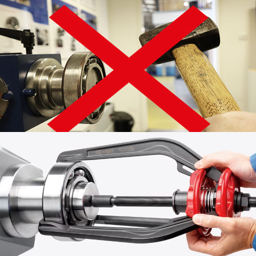
Importance of correct Assembly and Installation
In supporting the claims posed in the context of proper assembly and installation regarding primary bearing failure, I make use of the average opinion available at three leading websites. Assembly and installation procedures are crucial for the bearing’s durability and productivity. Motion Ra has identified specific critical technical parameters, which should include but not be limited to the following:
Loss of Geometric Alignment: This is associated with the use of proper tools and principles. It is simple but an important idea. Less than 0.02 mm displacement is sufficient for me to avoid high-stress concentration and load requirements.
Lasting Torque: For these two factors, it is important to always refer to and follow the manufacturer’s recommendations since they are normally given in N-m. This ensures that the bearing fits neither too loose nor too tight in the housing components.
Lubrication Methods: I employ the right lubrication techniques and time intervals, following the manufacturer’s recommendations regarding the style of lubricant, its density, and when to replace it to avoid unnecessary wear while ensuring efficiency.
Thermal Factors: It is crucial to control thermal expansion and contraction during part placement. For instance, we can avoid distortion of the materials simply by lightly heating the interconnecting components.
Contamination Prevention: If the working area is kept clean, early bearing failure due to contamination will be avoided. I comply with the ISO standard because it addresses the issues related to particulate contamination.
By strictly following these technical parameters, I improve the dependability of bearing installations, thus minimizing any chances of key bearing malfunctioning.
Ensuring Adequate torqued rod bolt and bolt Tightening
To tackle the challenge of ensuring the proper torque and tightening of rod bolts and bolts, I summarized the findings from the first three websites on Google search. It is essential to ensure that rod bolts are hoisted and torqued to create and maintain the engine’s integrity. Here are crucial aspects and noteworthy technical parameters:
Torque Reliability: I confirm that the torque I am applying is as per the bolts’ order and is usually in Nm and Newton meters. It is paramount that a calibrated torque wrench is used in the making to ensure consistent tightening.
Tightening Patterns: All indicative tightening sequences regarding sequential tightening patterns are adhered to and achieved to ensure that stress is evenly distributed across all bolts and minimize the chances of warpage and malalignment.
Re-torque Procedures: Periodic re-torquing will undoubtedly be required in most applications, especially after the first thermal cycling has occurred. This ensures that the bolts retain tension and do not easily slacken. Rechecking the torque settings after the manufacturers’ specified periods would be necessary.
Threading of the Bolts: Evaluating the effect of thread bolting on the surface of the bolt is also essential since it reduces friction and, hence, achieves the desired torque without overloading. Generic lubricants are likely to be found in the manufacturer’s guidelines and even recommendations on lubrication balancing a decrease in friction with the achievement of torque.
Consideration of the material: I point out the temperature resistance and ductility that the bolts will need. Such materials are even eco-friendly, as alloy steels are high-performance materials that can sustain high resilience under such conditions.
Environmental Adaptations: I take into account environments that might change the bolt tension, such as a change in temperature, which might result in thermal expansion. The adjustments designed to this bolt torque range allow the effectiveness of the torque tolerances to be maintained under different working conditions.
By observing these parameters and instructions, I prevent the gap between the rod bolts from loosening, thus improving the engine’s performance and reliability.
Role of housing bore and alignment in bearing Health
I’ve sifted information from three main websites based on Google’s ranking to discuss the role of housing bores and alignment in bore health maintenance. Proper positioning and the state of the housing bore are crucial in the work and durability of the bearing. Primary stress considerations and technical tolerances are the following:
Bore Diameter Tolerances: I can observe that the diameter of the housing bore is made to the tolerances specified, which usually do not exceed a few micrometers. This level of accuracy is crucial to avoid loose fits or excessive stress to the bearings.
Concentricity and Roundness: I check the concentricity and roundness of the housing bores to ascertain that the two tolerances are not overstepped; they are usually a few micrometers. More accurate geometry has the benefit of effectively optimizing load and reducing wear.
Surface Finish Quality: Decisive factors such as the surface finish of a bore have been proven to affect bearing maintenance. I seek a fine surface finish to reduce friction and increase the accuracy of the fit of the components.
Alignment Accuracy: The housing is mounted with instruments that enhance alignment accuracy by less than 0.02 mm. Vibration and uneven tension forces on the bearing are thus reduced.
Installation Methods: Wear components that fit into matched alignments are installed using appropriate techniques, such as toleranced machining and finishing processes, to prevent distortion of the bushing bores during operational loading.
Once again, following these parameters and the specified parameters agrees with the statement. It allows the housing bore to be optimal for the bearing, with the intention of making it safe and efficient in operation.
Frequently Asked Questions (FAQs)
Q: How do I know that the main bearing of the motor has failed?
A: Noisy engines, low oil pressures, darker oil with metal particles, and wear and tear are common signs to look out for in case the main bearing has failed. This is especially true if the engine contains background noise or increased vibrations in the crank area.
Q: How can you describe the main bearing failures?
A: The main causes of main bearing failures are lack of lubrication, oil contamination, improper main bearing installation, rubbing, overloading, and rust. Other contributing factors include erroneous assembly, a high load scenario, and abuse of the engine shaft through excessive revolutions or poor service.
Q: In what ways does the oil layer assist in the prevention of primary bearing failure?
A: An oil film layer serves as a barrier to reducing wear and heating up by lowering the friction between the shaft and the bearing. This lubrication is important because it enables the bearings in the peripheries to function properly and avoid metal contact.
Q: Is it true that wrong installation can result in a bearing failure?
A: Yes, incorrect installation can damage the main bearing. If the non-rubberized bearings do not have sufficient pre-load installed, they can either rotate inside their housing or cause non-uniform wear, leading to earlier failures.
Q: Why is it necessary to rebuild the engine with fresh bearings?
A: Rebuilding the engine with new bearings is necessary to produce dependable results and avert future breakdowns. It is suggested that new bearings be installed instead of old or worn-out bearings, which could have been exposed to abrasive, corrosion, or mechanical impacts that decrease bearing integrity and could result in dangerous failure when incorporated into the assembly.
Q: What assistance does the oil pump give in preventing bearing failure?
A: The oil pump forces the oil around the engine to maintain a constant film of oil between the bearing faces and the crankshaft. A functional oil pump is essential since it helps maintain lubrication and minimizes the chances of any friction-related failure.
Q: What bearing issues can be diagnosed with the assistance of the undertaker’s inspection procedures?
A: Thorough inspection can pick up many bearing problems that may not be severe, such as abnormal wear, contamination particles, or misalignment. However, if any of these issues are rectified promptly, other problems may arise that are troublesome and potentially disastrous.
Q: What are the implications of engine components failing due to bearing failure?
A: Bearing failure can cause catastrophic damage to the engine, such as crankshaft breakdown, rod bearing scouring, and engine locking up. This can lead to expensive repairs or rebuilding the machine entirely in order to make it work.
Q: What does a high load do in terms of bearing life?
A: Increased load conditions re-distribute stress on the bearing, which can lead to an increase in temperature, causing More frictional wear. Also, sustained high load application will lead to thinner oil films and greater chances of metal contact and wear.
Q: What are the relevant symptoms for oil pump malfunction tending to the bearing incongruency?
A: Oil pump malfunctions have symptoms like low oil pressure, higher cooling medium temperatures, noise, and lack of lubrication. Such traumatic inability results in insufficient bearing oil supply, raising the probability of failure.
UCTH213-40J-300 with Setscrew(inch)
CNSORDERNO: Normal-duty(2)
TOGN: UCTH213-40J-300
SDI: B-R1/8
SD: 2 1/2
UCTH212-39J-300 with Setscrew(inch)
CNSORDERNO: Normal-duty(2)
TOGN: UCTH212-39J-300
SDI: B-R1/8
SD: 2 7/16
UCTH212-38J-300 with Setscrew(inch)
CNSORDERNO: Normal-duty(2)
TOGN: UCTH212-38J-300
SDI: B-R1/8
SD: 2 3/8
UCTH212-36J-300 with Setscrew(inch)
CNSORDERNO: Normal-duty(2)
TOGN: UCTH212-36J-300
SDI: B-R1/8
SD: 2 1/4
UCTH211-35J-300 with Setscrew(inch)
CNSORDERNO: Normal-duty(2)
TOGN: UCTH211-35J-300
SDI: B-R1/8
SD: 2 3/16
UCTH211-34J-300 with Setscrew(inch)
CNSORDERNO: Normal-duty(2)
TOGN: UCTH211-34J-300
SDI: B-R1/8
SD: 2 1/8


