


The Ultimate Guide to Ground Shafts: What Every Engineer Needs to Know
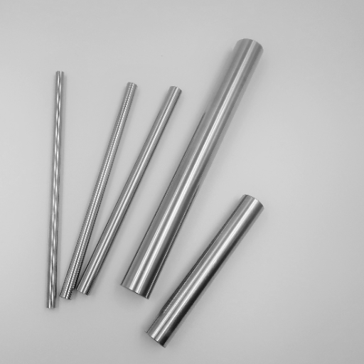
Ground shafts are a fundamental component in numerous mechanical and structural systems, playing a crucial role in ensuring stability, functionality, and alignment. From industrial machinery to transportation systems, understanding the design, application, and maintenance of ground shafts is indispensable for engineers seeking to optimize performance and durability. This guide aims to provide a comprehensive overview of ground shafts, including their material properties, manufacturing processes, key design considerations, and real-world applications. Whether you are an experienced professional or a newcomer to the field, this resource will equip you with the essential knowledge to make informed decisions and address challenges related to ground shaft implementation.
What are the main applications of ground shafts in mechanical engineering?
Common uses in rotary and linear motion systems
Ground shafts perform highly critical functions in systems for both rotary and linear motion while providing precision, reliability, and durability for various applications.
- Rotary Motion Systems: Ground shafts are primary components in drive systems like motor shafts, gear shafts, and CNC machine spindles and serve other functions as well. They enable the reliable and precise movement of the rotating member’s energetic force.
- Linear Motion Systems: Ground shafts are also profusely employed in peripheral guiding parts like linear bearings, rail-guided actuators, and even robotic arms. They enable movement in a straight line with stability and low friction.
These mechanically engineered industrial components are meticulously designed and constructed to meet a set of demanding technical requirements, which in turn ensure the shafts’ functionality in advanced mechanical systems.
Ground shafts in power transmission devices
Ground shafts are critical for power transmission systems because they provide rotational motion while eliminating misalignment, wear, and vibration in the machine. Efficient power transfer is crucial in gearboxes, motor drive units, and pumps, and ground shafts are commonly utilized in these devices.
- Material Composition: They are usually made from Alloy Steel or Stainless Steel, which are some of the high-strength, wear-resistant materials that ensure durability against high load and stress conditions.
- Surface Finish: The surface of ground shafts is generally finished to be less than 0.4 µm in Ra (Roughness Average) to enhance performance in high-demand applications.
- Diameter Tolerances: Achieve a seamless fit between the shafts and the bearings, collars, and couplings by maintaining shaft tolerances of ±0.001 in.
- Straightness: Shaft alignment in reasonably accurate rotational systems greatly depends upon straightness tolerances within 0.001 in over the shaft length.
- Hardness: Enhance wear resistance and fatigue performance in operation by keeping surface hardness between HRC 58-62 on the Rockwell Hardness Scale.
These are said to provide power transmission systems maximum dependability while maintaining the system’s core structure and ensuring operational efficiency in exceedingly challenging environments.
Applications in pump shafting and bearings
Precision-ground shafts serve an important function in pump shafting and bearing systems due to their capacity to withstand a relatively high level of torque.
- Straightness Tolerance: Misalignment, excessive vibration, and undue wear on the pump systems to the shaft length straightness tolerance of 0.001 or less is required in the pump shaft to enhance the system performance level.
- Surface Hardness: To improve wear and fatigue stress resistance, which is important in high-friction and high-pressure environments, a surface hardness of HRC 58-62 should be used.
- Corrosion Resistance: Shafts that are used in a seawater environment, or any other environment which uses aggressive chemicals, will require superior materials like stainless steel 316 or 17-4 PH and precision coated surfaces.
- Dimensional Accuracy: The sophisticated construction of bearings and pump shafting systems necessitates precision in dimensions, typically 0.0005 inches or better, so that coupling and bearing components interact as failed joints.
These defined factors greatly reduce the amount of time allocated during maintenance while simultaneously improving the life cycle performance of the bearing systems. This also allows them to operate effectively under difficult conditions. This makes precision shafts vital for fluid-handling systems, heavy machinery, and other devices that require the utmost reliability and efficiency.
How are precision ground shafts manufactured?
Materials used in ground shaft production
The production of precision ground shafts is based on selecting the materials that serve the desired strength, endurance, and other operational requirements. The following materials are most commonly used:
- Carbon Steels: High-grade carbon steels like 1060 and 1045 are often used because they have exceptional tensile strength along with great resistance to wear. These materials also go through heat treatment for achieving hardness of around 40 to 60 HRC depending on the use.
- Alloy Steels: Chrome molybdenum steel (AISI 4140) and other alloy steels are picked for their improved alternative toughness and fatigue strength. They are readily machinable and are able to be hardened into profile shapes for heavy-duty uses.
- Stainless Steels:Grades like 303, 304, and 416 are selected when resistance to corrosion is extremely important such as in chemical or high humidity environments. Stainless steels provide strength and good corrosion resistance, which makes it useful in the food processing and marine industries.
- Tool Steels: Exceptional wear resistance and hardness are the prominent features in tool steels D2 and O1. These materials are ideal for high dimensional stability under increased heat and load.
- Various Other Alloys: Aluminum and bronze as non-ferrous materials can be used for applications requiring low weight and low friction. However these materials are application specific and are generally used in low stress environments.
Material selection is determined by use conditions including, but not limited to, load, speed of rotation, level of exposure, and environmental conditions as well as the required finishing. The combination of accurate material choice and modern production methods guarantees the best quality of the shaft in operation.
The grinding process and achieving high precision
The grinding process is an essential method of manufacturing as it ensures that shafts and similar components are of high precision and finish. It consists of the removal of material using abrasive action using a rotating tool; in this case, a grinding wheel with very high speeds. The main goal is to obtain the exact desired dimensions, precise tolerances, and an elevated surface finish.
- Surface Roughness (Ra): The achievable range, in the case of precision-ground surfaces, is typically 0.2 – 0.4 µm. It is dependent on the amount of abrasive material, grit size, and the feed rate utilized during the grinding process.
- Dimensional Tolerances: Depending on the machine’s accuracy and setup, grinding can achieve tolerances tighter than ±0.001 mm.
- Grinding Wheel Selection: The workpiece material and its desired surface finish must correlate with the choice of abrasive material (aluminum oxide, silicon carbide, or diamond) for the grit size selection.
- Coolant Usage: Cooling fluids are needed to remove excess heat and avoid thermal alterations to the dimensions to retain them.
- Feed Rate and Depth of Cut: These values need to be set so that the rate of cutting is matched with the accuracy of the piece. Normal feed rates are from 10 to 50 mm/min based on the material of the workpiece and the properties of the grinding wheel.
Where high-precision CNC grinding technology is implemented, precision and repeatability are further boosted, along with automation for volume production.
Case hardening and other surface treatments
Anodizing and hood hardening are two additional treatments that aid in enhancing the wear resistance and durability of surface components subjected to heavy stresses. In case hardening processes, carburizing or nitriding is usually incorporated Chinese to increase the surface hardness whilst maintaining a tough and ductile core. In carburizing, a treatment temperature of 870 degrees celsius to 950 degrees celsius is common, along with a duration that depends on the depth of the case, which is normally 0.1 mm to 3 mm. Also, the concentration of carbon gas and the flow rate for diffusion is controlled unlike this, the general range of temperature in nitriding is lower 500 degrees celsius to 570 degrees celsius while nitrogen is also being implanted to the surface layer. Nitriding is better suited for components that are easily distorted and need to be strengthened.
Alongside the processes stated earlier, there also exist various surface treatment methods that include but are not limited to Hydrogen plasmas, anodizing, and chrome plating. The best surface treatment method of anodizing is adding to aluminum since it helps in raising the structures against corrosion and increasing its dielectric strength. Moreover, adding chrome on steel parts has shown to greatly improve its life resistance and makes it an excellent surface treatment method with changes between 20 to 250 micrometers. With the help of a vacuum chamber, controlling the temperature along with time and the ratio of plasma gas in the chamber, one can set their plasma nitriding with enhancement over the life resistance and the hardness.
My analysis stems from the material constituents, the product’s intended use, and the performance expectations which allows me to understand the questions better. The reasons would, in each case, arise from the possible synergy between material characteristics and functional needs of the part to ensure best results.
What are the key factors to consider when selecting a ground shaft?
Diameter and length specifications
In the selection of a ground shaft, I would start with a thorough examination of its diameter and length to ensure that they fulfill the functional and structural requirements of the application. The diameter choice cuts across the anticipated load capacity, pre-requisite for torque transmission, and its tolerance to deformation. For instance, a high level of stiffness or resistance to bending places a premium on larger diameters, while low levels permit the use of smaller options. Additionally, larger diameters are preferable in cases where the designer is working with stiff applications alongside limited spaces, and lower diameters are favorable in less reality-constrained situations.
When it comes to length, the alignment of precision, spatial restrictions on the design, and the likelihood of deflection over long spans should be factored in. Lengths without proper support can lead to excessive deflection or vibration during operations. As an ideal scenario, the usage of standard lengths is recommended as it fosters effectiveness and efficiency of the manufacturing process as well as reduces costs.
- Length Tolerance: Usual tolerance is +/- 0.1 mm, tighter fits are used for drafting precision requirements.
- Material Selection: The weight restrictions needing environmental resistance, such as carbon steel, stainless steel, or aluminum alloy,y should be accounted for in the material selection.
- Diameter Tolerance: ±0.01mm or as per application-specific requirements, ensuring proper fit and minimization of play.
These suggestions are justified by their direct correlation to achieving the component’s mechanical and operational integrity while ensuring cost-effective manufacturability.
Tolerance levels and surface finish requirements
To determine tolerances and surface finish specifications about application needs, engineering specifications set forth are to be followed within a defined range of mechanical accuracy, performance, and reliability:
- Geometric Tolerance: The geometric features of concentricity, flatness, and perpendicularity should be set to ensure compliance with ISO 1101 regulations or equivalent. Assembly of higher order geometric constructions will require that the geometric tolerances are maintained within a range of ±0.005mm.
- Dimensional Tolerance: For components that undergo high stresses or tight assembly tolerances, ordinary dimensional tolerances will be mandatory within a range of ±0.01mm, or tighter as imposed by the designs.
- Surface Roughness: The surface finish of the interfacing parts is characterized by Ra ≤ 0.8 µm in critical metallic components to minimize the extent of friction and wear enabled on sliding surfaces, as well as sealing surfaces. Non-critical areas may be finished to Ra ≤ 3.2 µm.
These factors effectively address mechanical, manufacturing, and functional challenges while reducing assembly difficulties and enhancing the operational effectiveness in the same manner. Surface validation should be conducted to ensure compliance by utilize multitip Coordinate Measuring Machines (CMM) or surface profilometers.
How do ground shafts improve bearing performance and longevity?
Reducing friction and wear in ball bearings
Precision machined shafts lower friction, affecting the life and performance of ball bearings by ensuring optimal contact conditions between components. The goal is to achieve a surface roughness of Ra ≤ 0.4µm, which helps reduce abrasive and adhesive wear due to improved surface texture. Furthermore, precision grinding also improves dimensional accuracy and concentricity, which are essential for proper load utilization on the rolling elements. This results in the erection of lower stresses and enhances the longevity of the bearing.
- Roughness Average: Ra ≤ 0.4µm (for reduction of friction and wear).
- Concentricity Deviation: ≤ 0.01 mm (for maintenance of adequate alignment to avoid excessive misalignment).
- Material Hardness: simple bearing shaft steels 58-65 HRC (e.g., 52100, SUJ2) to enhance resistance to wear and high load conditions.
- Wider tolerance: ±0.005 mm (for easier fitting into other parts).
Meeting these criteria allows ground shafts to function consistently under industrial and mechanical systems, thus enhancing the service life of ball bearings. Optical microscopy or optical profilometry is a standard way to check adherence to those requirements.
Enhancing alignment and preventing misalignment issues
Efficacious alignment is essential in a mechanical system as it enhances performance, minimizes wear, and reduces inefficiencies. Misalignment can be mitigated through high-precision assembly practices coupled with the use of quality components that meet the defined technical standards. To improve alignment and eliminate the chances of misalignment, it is recommended that the following measures are taken:
- Shaft Straightness: To avoid any bending stresses, change in the shaft’s line should not witness an allowance of more than 0.02 mm per meter of length.
- Bearing Housing Fit: For proper mounting, make sure to meet the bore allowance of H7 to avoid allowing a concentration of stress.
- Parallelism and Angularity of Mounting Surfaces: To enable accurate aligners, interference for accuracy of parallel and angular placement should be not be greater than 0.01 mm and 0.05°, respectively.
- Load Distribution: Locally concentrated stress will be avoided by distributing the load uniformly through the use of shims, spacers, or self-aligning bearings.
- Dynamic Runout: Measure of excessive runout leading to vibration issues should be set at an allowance of 0.005 mm. Anything greater will result in heavy machinery use, combined with fast wear.
To ensure minimal chance of misalignment, inspection of laser and dial indicators regularly will prove efficious as well as enable sustained system dependability.
Extending the lifespan of mechanical components
The proper maintenance and repair practices for mechanical components increase its operational lifetime. The following suggestions and specifications may be adopted:
- Lubrication: The application of suitable lubricants on a regular basis prevents friction and wear of the moving parts. Use lubricants of the viscosity grade specified by the manufacturer, provided it operates as intended within the given temperature range.
- Alignment Tolerance: Paralleling between rotating components needs to be done accurately, about stress concentration along the components, to prevent premature failure. To prevent those issues, keep alignment tolerances within specifications, such as parallelism not exceeding 0.01 mm and angular misalignments capped at 0.05°.
- Surface Finish Standards: Reduce wearing of surfaces flanking components by making sure they are below 0.8 µm roughness(Ra) values.
- Load Management: Work within the recommended load limits of each component. Example: factor of safety (FoS) ≥ 1.5 for dynamic loads.
- Vibration Control: Directly monitor vibrations with a condition monitoring systems, maintenance can be performed by dynamic balancing the parts of the machine. Set vibration limits to ISO 10816, which sets the upper boundary of 4.5 mm/s of vibration velocity to machines in good working condition.
- Corrosion Protection: Reduce environmental effect by applying anti-corrosive coating and storing properly to minimize degradation.
- Use of Calliper: Use a caliper, dial indicator,s and thermography with ultrasonic methods to monitor misalignment, wear and tear, or other emerging deficiencies. These measures should be scheduled according to operational cycles, which are normally set at 500 service hours or by the machine’s specifications.
By integrating these aspects into each step of the process, many structures’ dependability and longevity are improved, thus enhancing their performance and cutting down service interruptions.
How to properly maintain and care for ground shafts in various applications?
Lubrication and cleaning best practices
For different applications, maintaining the quality and functionality of ground shafts includes regular lubrication and cleaning. Best practices include following the guidelines outlined below:
- Selection of Lubricant: Lubricants must be used cautiously and in moderation. For various mid-duty applications, oil ISO VG 68 or 100 is widely used depending on the temperature and load conditions. Lubricant must meet ISO 3448 standards for viscosity classification. Ensure to select the type of oil specified by ground shaft manufacturers which is usually grease or oil with specific viscosity grades.
- Frequency of Lubrication: The intervals for applying the lubricant should be inevitable to the operational cycle of the machinery. Unless mentioned otherwise in the maintenance manual, lubricant should be applied after every 500 service hours. Consistent delivery can be facilitated by automated lubrication systems, especially in critical applications.
- Control of Contamination: If contaminants are not controlled, they can easily ruin the overall functioning of various applications. The modification points should always be cleaned after applying the lubricants. Grease nipples should be washed thoroughly, free from any debris, and ensure to use cloths or wipes that do not leave lint.
- Procedure for Cleaning: Petersides set clean must ensure that abrasive particles cannot ruin the surface of the shaft. For cleaning purposes, the shaft cleaning solutions should be the preferred option, as using harsh chemicals can prematurely weaken materials and should be avoided.
- Inspection of the Surface and Storage: After cleaning, survey the shaft thoroughly for any signs of wear, scratches, or pitting.
If the shaft has to be kept for a long time, use a thin anti-corrosive film or coating. Make sure to store the shaft in clean and dry conditions where the humidity is less than 50% and the temperature is between 15 degrees Celsius and 35 degrees Celsius. By following these technical guidelines and instructions, the wear and downtime can be minimized while keeping the shafts on the ground in their prime operational conditions.
Inspection and replacement guidelines
To achieve maximum productivity and lifespan of the shaft, the following inspection and replacement criteria should be adhered to:
- Visual Inspection: Carry out a regular internal visual examination to determine whether there are any surface defects, such as scratches, cracks, deformation, or pitting. Micro-damages that are not easily visible to the naked eye should be checked using magnifying lenses or other appropriate equipment. Also, ensure that the shaft surface is clean and free from contamination that may hide some defects.
- Dimensional Accuracy Check: The critical dimensions of the shaft’s surface are the diameter, length, and the shaft’s concentricity. These should be checked with precision instruments such as micrometers or calipers. Do not forget that the tolerance values must always meet the specification design requirements of the manufacturer. For example, concentricity is seldom more than 0.02 mm in defiance of operational imbalance.
- Material Integrity Testing: Evaluate the integrity of the shaft using non-destructive tests such as ultrasonic or dye penetrant methods for internal and external features. This is especially import to expose subsurface flaws that would endanger the structural integrity with loading.
- Verification of Overall Rotational Balance: When the shaft has a moving part, carry out a dynamic balance test. Imbalance in the shaft and its components will lead to wear and tear due to increased vibrations when the equipment is in use. Resolve imbalances based on the normal balance grade, which is G6.3 as per ISO 1940-1 for routine industrial usage.
- Reporting: Ensure that all inspections, measurements, as well as repairs are documented correctly and kept updated to assist in maintaining compliance with maintenance requirements.
Adhering to these guidelines will guarantee optimal performance, reduce irregular downtimes, and improve the overall performance of the shaft.
Frequently Asked Questions (FAQs)
Q: What are the three main types of ground shafts available in stock?
A: The three main types of ground shafts typically available in stock are carbon steel, stainless steel, and aluminum. Each type offers different properties and is suitable for various applications in mechanical engineering and construction.
Q: What is the difference between ground shafts and other types of shafting?
A: Ground shafts are precision-manufactured to tighter tolerances than standard shafting. They offer a smoother surface finish, better roundness, and straighter construction. This makes them ideal for applications requiring high accuracy, such as in pulleys, sprockets, and many mechanical components.
Q: How do I learn the differences between various ground shaft materials?
A: To learn the differences between ground shaft materials, consider factors such as strength, corrosion resistance, and weight. For example, stainless steel shafting offers excellent corrosion resistance, while carbon steel provides high strength. Consulting material data sheets and speaking with experts can help you understand these differences.
Q: What are some common applications for ground shafts in mechanical engineering?
A: Ground shafts are used in many mechanical applications, including engine components, pulley systems, conveyor belts, and precision machinery. They are essential in situations where smooth rotation and precise alignment are critical for optimal performance.
Q: How can I protect ground shafts from corrosion, especially in water-exposed environments?
A: To protect ground shafts from corrosion, especially in water-exposed environments, consider using stainless steel shafting or applying protective coatings. Regular maintenance, such as cleaning and lubrication, can also help extend the life of the shaft and protect it from corrosive elements.
Q: Are metric sizes available for ground shafts?
A: Yes, metric sizes are available for ground shafts. Many suppliers offer both imperial and metric sizes to accommodate different design specifications and international standards. Be sure to specify the correct measurement system when ordering.
Q: Can suppliers offer custom cutting for ground shafts?
A: Many suppliers offer custom cutting services for ground shafts. This can include saw cut lengths to your specifications or even drill and tap operations. Always check with your supplier about their capabilities for customization to meet your specific project needs.


UCTH213-40J-300 with Setscrew(inch)
CNSORDERNO: Normal-duty(2)
TOGN: UCTH213-40J-300
SDI: B-R1/8
SD: 2 1/2
UCTH212-39J-300 with Setscrew(inch)
CNSORDERNO: Normal-duty(2)
TOGN: UCTH212-39J-300
SDI: B-R1/8
SD: 2 7/16
UCTH212-38J-300 with Setscrew(inch)
CNSORDERNO: Normal-duty(2)
TOGN: UCTH212-38J-300
SDI: B-R1/8
SD: 2 3/8
UCTH212-36J-300 with Setscrew(inch)
CNSORDERNO: Normal-duty(2)
TOGN: UCTH212-36J-300
SDI: B-R1/8
SD: 2 1/4
UCTH211-35J-300 with Setscrew(inch)
CNSORDERNO: Normal-duty(2)
TOGN: UCTH211-35J-300
SDI: B-R1/8
SD: 2 3/16
UCTH211-34J-300 with Setscrew(inch)
CNSORDERNO: Normal-duty(2)
TOGN: UCTH211-34J-300
SDI: B-R1/8
SD: 2 1/8