Tips for Maintaining Cam Roller Bearings
Caring for cam roller bearings and track rollers is essential for functioning machines in different sectors. These parts are critical for allowing movement and eliminating friction but are sometimes subjected to high forces and challenging environments. This guide provides a deep insight into the tips and procedures necessary for these essential elements. From their functional responsibilities to their preventive measures and troubleshooting, the article offers a practical structure that can be used to safeguard equipment and reduce operational time wastage while improving performance. Whether you are a machinery expert or a timeline, this pro guide will improve your understanding and enhance maintenance methods.
What are cam roller bearings, and how do they work?
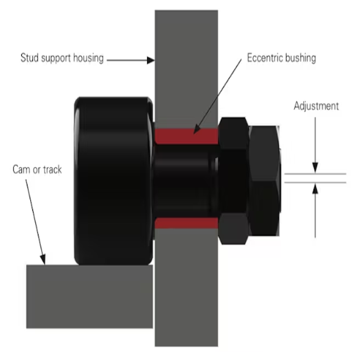
Understanding the components of cam roller bearings
Bearings attached to the cam followers are defined as cam follower bearings. The inner and outer rings, a cage, and sometimes rolling elements, mostly cylindrical or needle roller, are parts of the ball-bearing assembly. The inner ring has a plain rolling hole or a stud, whereas the outer ring has a thick wall structure to withstand huge forces.
A bearing’s load capacity rating is usually measured in Newton’s N. A stand would note this rating as both s.wl and wl where s.wl refers to the static and wl in dynamic and will give the cam roller bearing the strength it needs.
The bearings are primarily constructed from chromium alloy or high steel, tempering them and providing tensile strength.
The outer ring is secured along these lines, supporting the workpiece of the bearing. The rings generally have dimensions spanning between 10 mm and sometimes 150 mm.
Period and extensive temperature range are crucial to aid bearings, so their durability is high. Most commonly -30 to 120 degrees.
More grease or oil must be employed to decrease the heating produced by friction.
Based on the components and parameters, engineering bearings for cam-driven mechanical devices enhance error-free performance, reliability, and sturdiness. Always keep their particulars in mind when determining which bearing your application requires.
The role of needle rollers in cam follower bearings
Rollers, particularly needle rollers, form an essential part of cam follower bearings by helping improve the load-bearing capacity and functioning of the cam follower. This cylindrical roller type has a very high length-to-diameter ratio in dimension. In this manner, the needles ensure an out-of-plane loading of the inner raceway. Thus minimizing contact and wear, especially under elevated loads on the bearing surface.
Diameter: Diameter adjustment is standard when the bearing has an outer dimension limit between 1 mm and 10 mm.
Length/Width Ratio: The ratio is typically about 3 to 10 times the diameter on average to limit strain and ensure maximum load placement.
Material: These are often made from pressure-holed grade hardened steel, for example, AISI 52100, to have remarkable hardness and wear resistance.
Surface Finish: Bearings are made with a surface finish of precision ground to attain slickness and reduce the frictional aspect while helping make transfers smooth.
Hardness: They typically harden between 58 and 65 HRC to sustain high pressure and extend longevity.
Needle rollers also improve the reliability and efficiency of cam follower bearings by distributing loads radially and axially when fitted into self-automated machines, conveyor systems, and robots. The construction and accuracy of these cam followers are the only limitations, which usually allow them to withstand great strains and torque without compromising on performance.
Differences between cam rollers and track rollers
Cam and track rollers are similar in application to cam followers, but mentioning the differences between them from a design and usage perspective is worthwhile.
Design and Construction:
Cam rollers can withstand high contact stresses thanks to their thick outer rings, which help them follow cam profiles.
Track rollers, designed to move linearly along with the guides, are constructed using outward flanges and thin outer rings.
Load Capacity:
Cam rollers’ sturdy design allows them to endure both radial and axial forces, which is why they are preferred for handling heavy-duty, complex load conditions.
For typical linear movement applications, the focus is more on accuracy and stability, in which track rollers are engineered for radial loads.
Application Scenarios:
The applications where cam rollers are used include Cams, indexing mechanisms, or other forms of contoured motion.
On the other hand, track rollers are used to implement sliding doors, guide tracks, and conveyor systems.
Technical Parameters:
Cam rollers usually have outer rings hardened to a maximum of 58-65 HRC to withstand extreme contact pressure.
Since the loads applied to track rollers tend to be more constant and less demanding, surface hardening is slightly less, between 55 and 60 HRC.
Moreover, while cam rollers are used on compact systems with diameter ranges of 10 mm to 100 mm, track rollers are used on larger systems with diameters between 5 mm and 50 mm.
How to properly lubricate cam roller bearings?
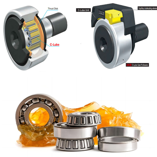
Choosing the right lubricant for your application
Choosing the proper lubricant for cam roller bearings is critical to guaranteeing good performance, prolonging service life, and preventing excessive wear. The choice varies widely based on multiple factors like load, speed, temperature, and environment:
Load and Speed: In high-load and low-speed conditions, grease with a greater viscosity (like ISO VG 150-460) is suggested to achieve a strong and durable lubrication film. Since friction and heat build-up may not be avoided in high-speed applications, greases, and oils with lower viscosity (ISO VG 32-100) is more beneficial.
Operating Temperature: Temperature impacts the performance of some lubricants. In this case, below -20°C (-4°F), low-temperature-resistant greases, such as lithium or PAO-based greases, could work well. Also, for environments where the temperature is higher than +120°C (248°F), high-performance greases containing polyurea and calcium-sulfonate thickeners are the best fit.
Environmental Conditions: In dusty or wet surroundings, calcium-complex and lithium-complex Greases effectively prevent contamination due to their excellent sealing abilities and high water resistance. Lubricating grease with corrosion-resistant properties would be more suitable in corrosive environments.
The term for lubricant replenishment should also be based on operational requirements, for lubricants typically last from weeks to twice a year, depending on the rhythm and wear factors. Manufacturer’s guidelines should always be followed to harmonize the bearing, the lubricant used, and the application.
Proper lubrication techniques for extended bearing life
To enhance bearing life, it is essential to use appropriate lubricating methods. First, the bearing surfaces must be verified to be clean and uncontaminated for every lubricant application. Likewise, the lubricant selection should align with the environment, the load it will carry, the working speed, and the temperature conditions. For instance:
Operating Temperature: Consider the multi-purpose grease whose base oil viscosity corresponds to the operating temperature range. For lubricating high-temperature resting conditions, ensure the oil works well at 250°F (120°C) or more.
Load: Lubricants with extreme pressure (EP) additives may be necessary for high-load applications.
Speed: Use the speed factor (DN value, where DN = bore diameter in mm x RPM) to select the appropriate type of grease; if the DN values are low (<300,000), heavy greases can be used, but on higher DN values (>500,000) the drugs should be lighter to enable the lubricant to work better thermally.
Contaminants: In a more damp or hostile atmosphere, it is preferable to use sealed bearings or special-purpose greases with anti-corrosion and anti-wear properties.
Moreover, applying the appropriate lubricant in appropriate amounts is necessary, as excessive application would lead to heat generation. In contrast, inadequate application would increase friction and wear. In the case of grease lubrication, the bearing cavity is only partly filled to between 30% and 50% of its volume. Follow the prescribed relubrication schedules, which usually vary with the application; for instance, high-speed bearings require relubrication once every 500 to 1,000 operating hours, while low-speed bearings may only need to be lubricated after operating for up to about 2000 hours.
Regular assessment of lubrication efficiency and periodic checks of wear, leakage, or contamination will all add to the expectation of efficient running of the bearing for a long time. Always refer to the manufacturers’ technical instructions for more specific information.
Signs of inadequate lubrication in cam rollers
Deficient lubrication on cam rollers can lead to premature damage; hence, identifying and rectifying such cases is of prime importance. Some of the common indications are:
Excessive Noise – Increased friction may cause cam rollers to emit loud screeching or grating sounds.
Abnormal Temperature Rise—When the operating temperature suddenly rises, it signifies insufficient lubrication or a break due to debris.
Uneven Wear Patterns – Irregular wear-off patterns or indentation may occur due to absent lubricants.
Vibration and Misalignment – Deficient lubricants give way to non-uniform movement, and while this may result in vibration, it may also cause misalignment.
Key Technical Parameters to Monitor
Operating Temperature: The roller’s temperature should always be within the specified range (for boards, 60-90° C for Application; check for competitive specs).
Lubricant Viscosity: Lubricants should conform to the required viscosity according to operating load and speed, usually stated in cSt at 40 degrees Celsius.
Re-Lubrication Interval: Different time intervals must be established based on load and speed, such as 500 to 1000 hours for high-speed and 1500 to 2000 hours for low-speed systems.
Contamination Levels: Due to the possible degradation of the lubricant’s quality, there should also be an increasing level of alertness when measuring debris and moisture ingress.
There is no doubt that cam rollers can pose a challenge, however being mindful of signs and monitoring these parameters ensures that failure is reduced and cam roller system runs smoothly and efficiently.
What are the common causes of cam roller bearing failure?
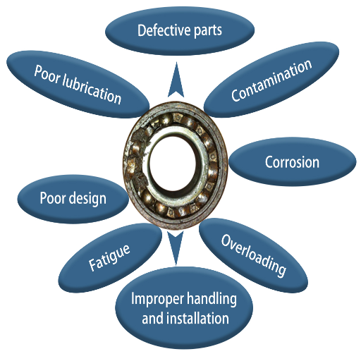
Estimating overbearing loads and stress on the bearings
Bearing gets damaged when it is subjected to stress or loads more than its rated capacity. This article aims to understand them to avoid future bearing failures. The general reason why overloading occurs is when the working conditions exceed the operating recommendation. Say, for example, if a bearing is designed to withstand a dynamic force of fifty thousand units and is used with a force of fifty-eight thousand units- the excess pressure generated could lead to metal automotive bearing turning into dust, ultimately resulting in the automotive system collapse.
Ignoring the vital part of structural integrity, the bearing, and not using symmetric loads could destroy the bearing structure and create other defects. To avoid this kind of problem, following the parameters the manufacturers set is vital. Issues arise when crossing tolerable limits, such as two hundred units. The response to these problems is loss of continuity in bearing rotation.
Rotational speed also increases stress if it exceeds the threshold. For example, bearing ratings state that rotating systems should stay below three thousand units. Still, in reality, they reach four thousand units. Therefore, sufficient capabilities, guided load settings, and maximum speed indicators related to the bearings must be carefully organized to achieve the best results while following the guidelines.
The effect of pollution on the performance of the bearing
Contamination is one of the principal factors that can negatively affect the functioning of bearings, causing them to wear out sooner than anticipated and incur losses in operational efficiency. The bearing unit can also be exposed to external particles like dust, dirt, metal scraps, and moisture, leading to wear, abrasion, and corrosion of surfaces. This, in turn, reduces both the bearing life and its load-bearing ability. In some cases, particle sizes as tiny, say, ten microns, can cause surface wear, whereas in others, more significant contaminants may leave imprints, termed brinelling, on the raceways.
Proper sealing arrangements are critical to prevent contamination from occurring. They can keep the sealed volumes free from the outer contaminants. The use of contact seals or labyrinth seals is more effective. Also, lubrication is essential in preventing the infiltration of unwanted particulates. The lubricant quality and the viscosity grade must be such that a film is maintained between the rolling elements and the raceways, preventing contact and consequent wear.
However, when a bearing is contaminated, reduced rotational efficiency can increase vibrations and even noise. Vibration analysis equipment can detect such symptoms, as standard vibrational amounts are often less than 5 mm/s RMS for standard bearings. For maximal protection, scheduled servicing and cleaning, coupled with the use of specially designed bearings intended to reduce the risk of contamination, must be done.
Addressing misalignment issues in cam follower applications
Misalignment is a significant issue in cam follower systems, as it can have a vital impact on the system’s performance, durability, and reliability. In response to this, please consider the following alternatives and their corresponding technical parameters:
Correct Installation Parameters: Proper positioning of the follower by ensuring that it matches parallel with the mating surface and does not result in undue stress on the bearing. Also, the precision alignment tools should be in such a way that they maintain the deviation within ±0.05 mm or the specified tolerance by the manufacturer.
Use of Cam Followers with Self-Aligning Features: For applications that are supposed to be self-aligning due to being in such environments, using cam followers with self-aligning spherical outer rings and floating bearings is preferred. These designs can withstand angular misalignment as much as ±3 degrees, aiding in even load distribution.
Periodical Analysis of Load Distribution: The load distribution on the cam follower should be periodically checked, as optimal load distribution avoids stress concentration. To avoid deformation risks and increased wear and tear, avoid applying an overload of more than 70% of the C rating.
Utilization of Flexible Uses: Flexible mounts or shim adjustments can limit fixed misalignment, allowing the effects of axial alignment to be sustained while reducing the radial force on the follower.
Condition Monitoring: Integrate vibration analysis and thermal sensors to detect alignment issues proactively. For adequate operations, a vibration of 4-5 mm/s RMS should be maintained, while any temperature rise more than 10 degrees Celsius from the normal range may indicate alignment problems.
If the strategies and parametric settings are followed, the risks posed by any misalignment in cam follower applications can be mitigated, and the system’s general workings can be enhanced.
How do you select the proper cam roller bearing for your application?
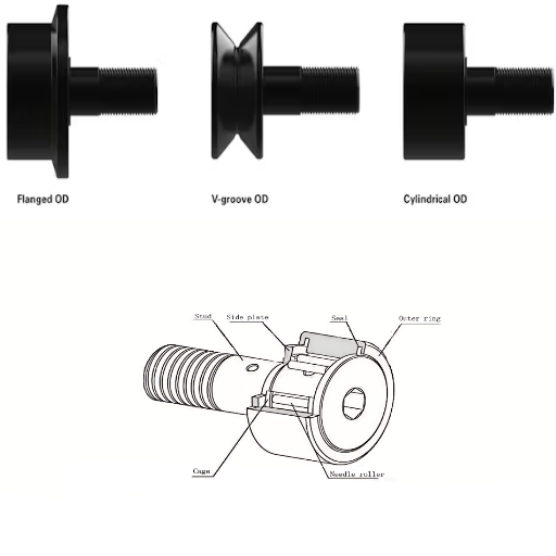
Cam roller bearing load capacity and speed requirements
If a cam roller bearing is to function adequately, then the load capacity and the speed requirements have to be understood first. First, check the static and dynamic load ratings that the manufacturer offers. This means the loads this bearing can support when not in motion or the loads it can bear when in motion. If the application is subjected to heavy or varying loads, these bearings should be used with a higher dynamic load rating.
The limiting speed of the bearing should be taken into account to determine the operating speed, which is determined by the lubrication, internal design, and operating temperature. Make it a point to ensure that the maximum operational speeds of your application is always less than the speed rating of the bearing, this way it will become efficient and will not overheat. For example, high-speed applications would require bearings that can easily withstand more than 10000rpm. In contrast, other lower-speed machinery require relatively lower numbers, which would be between 500 and 2000, depending on the load distribution.
All these factors, especially load and speed, along with the technical specifications, form the basis for determining whether a cam roller bearing will provide an adequate service.
Environmental factors when choosing bearings
As bearing selection is also based on environmental factors, I consider several key elements that meet the expectations and longevity requirements. First, I evaluate the working conditions, such as dust, moisture, or corrosive substance exposure, as they alter the performance of the bearing. For example, in cases of high environmental pollution, the use of sealed or shielded cam roller bearings is recommended to exclude penetration of contamination. In addition, in the case of very corroded areas, such bearings made of stainless steel or specially coated would be usable as these have high corrosion resistance.
Another factor is the temperature range. I also address the issue of bearing temperature limits, primarily if the bearing may operate in extremely cold or hot temperatures. It is essential to select a bearing with the required material and lubricant to work even under these conditions. For instance, bearings meant for high-temperature usage may contain grease that can withstand high temperatures or undergo unique heat treatments.
During this procedure, there are particular technical parameters that I assess and justify:
Seal type: To keep out dust and moisture in seals-heavy environments.
Material composition: Stainless steel or other materials with corrosive-resistant coats.
Temperature tolerance: Confirm operational efficiency within the intensity range stipulated.
Lubrication type: Thermally resistant and low-temperature operational lubricants, as needed.
Taking these environmental conditions and correlating them to these parameters, I provide dependable performance and greater durability of the cam roller bearing designed and selected.、
Choosing between stud-type and yoke-type cam followers
Between stud-type and yoke-type cam followers, I consider several elements primarily based on the application needs and the technical parameters involved.
Load capacity: The yoke-type cam followers tend to have more loads than the stud types, as they transfer forces through a more significant contact area. Thus, they are useful for heavy-duty operations.
Installation space: The stud-type cam followers are compact and self-contained, making their installation easier in space-constrained applications.
Zones of ease of mounting: Inherent threaded studs on stud-type cam followers make their mounting faster and easier. In contrast, yoke-type cam followers include support features that can be shafts or pins to perform similar functions.
Application of a slip fit: Yoke-type followers offer more ease in slip fits than stud type due to their design, which is not restricted, thus allowing for a better performance of the followers.
Maintenance Requirements: I pay close attention to the availability of lubrication options for the two types. Making a one-on-one selection is crucial to avoid damaging the automatic or manual lubrication systems.
Thus, by evaluating these parameters and considering the working conditions, I can develop an analytical solution that compromises performance, ruggedness, and implementation ability to ensure maximum output for the specific application.
What are the best practices for installing cam roller bearings?
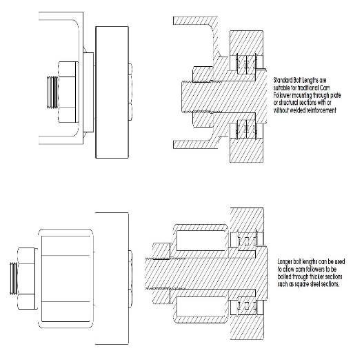
Proper mounting techniques for stud cam followers
I use a system that guarantees maximum performance and durability to ensure the stud cam followers are secured correctly. First, I check that the cleaned fastening surface is flat and rigid to avoid plastic distortion. Then, the stud is fitted with a nut and a wrench to apply a torque equal to the manufacturer’s set value to avoid tightening too much and stripping or deforming the threads.
There are, however, points to view when considering technical characteristics. Among them are:
Tapping Length: I ensure that the stud threads are wholly cut into the nut, which allows the engaging surfaces of both joints to be maximum throughout the joint or the nut.
Recommended Torque Values: Always ensure that adequate values are set for torque as recommended by the manufacturer to avoid adverse effects on the components’ performance.
How and where to place the lubrication points: The lubrication port (if there is one) is placed so that the servicing personnel can easily access it during the device’s servicing.
These steps, coupled with the adjustments mentioned above, lead me to believe that a robust yet efficient installation can be achieved to meet the application’s requirements.
Ensuring correct preload and clearance
I employ a systematic technique that enables me to complete my work whilst remaining precise and consistent in achieving the correct preload and clearance. Preload is essential as it serves to fasten components in place and prevent them from loosening as the machine operates, while deepening clearance is critical as it prevents parts from rubbing against each other or wearing out too much; here is how I address these aspects:
Preload calculation: The amount of assembly preload I consider depends on the intended amount of tension the assembly will receive, the actual components’ material properties, and the conditions under which it will be used. This is done to equip the joint to adequately resist dynamic loads without sustaining damage.
Torque accuracy: To achieve the preload that I set, I use a calibrated torque wrench to stress in the appropriate amount of rotation to it, and this is essential because aiming for the correct amount of rotation ensures proper load distribution to avoid threads from being over or under-compressed.
Clearance verification: The required preload may create tension that shifts the assembly threads from their original positions, causing expansion or other noises. I, therefore, take and record measurements using instruments such as feeler gauges or micrometers to bypass the strengths and limits of the design.
Compensating for thermal expansion: I note the frequency of thermal expansionary influences that must be considered in line with temperature tendencies and material features to which tight tolerances must be maintained regardless of the operating conditions.
Comprehensively contacting these parameters guarantees that I achieve an optimal performance and a robust installation. This systematic approach structures the elimination of mechanical failure tendencies while striving for the highest system efficiency possible.
Tools and equipment needed for proper installation
To avoid mistakes and achieve a confident installation, I make sure to have the following tools and equipment:
Torque wrench: It is critical to use a calibrated torque wrench to apply appropriate torque value indications. This ensures that certain preloads have been applied without excessive tightening or under-compression. For instance, I use wrenches with torque measuring capability, with a ±4% accuracy level corresponding to the application requirements.
Feeler gauges and micrometers: These great tools verify the clearances and tolerances. Clearance gauges, or feeler gauges, determine the dimension of small gaps, and micrometers furnish accurate measurements of components within a range of 0.001 inch or narrower precision bands for alignment to be within the design requirements.
Dial indicator: It checks the alignment and runout and evaluates the system’s components to ensure they remain concentric on each other and have an acceptable deviation from the designed system. It improves rotational balance and reduces abrasion.
Thread lubricants or anti-seize compounds are also applied to threaded bolts and nuts to eliminate friction, which may cause galling. Hence, torque preload determination will not be altered. These are specially made to withstand a particular temperature and to be compatible with the respective materials.
Material compatibility charts: These references aid me in determining the required gaskets, bolts, or lubricants for the specific operational environment by considering thermal expansion, corrosion, and load-bearing capabilities.
Similarly, from my perspective, poverty begins with failing to install a suitable tool for the task. This assumption is reasonable, as it is possible to achieve low alcohol loss rates while maintaining the operational stability of the installation throughout its service life. In this case, all the necessary stages must be completed in the installation and maintenance processes, and all facilities must be equipped.
Frequently Asked Questions (FAQs)
Q: What are the features and benefits of cam roller bearings?
A: Several cam roller bearing features and advantages include the capacity to support mainly radial loads, survive friction, and combined load applications. They usually possess a thick-walled outer ring, which effectively provides resistance against bending stress and longevity. Most cam roller blades also have a crowned external surface to assist in load distribution and reduce the edge stresses.
Q: What’s the correct way to lubricate rollers and followers of cams?
A: The lubricants or grease utilized for rollers and cam followers should be of a quality that bears the field condition. The lubricants should be evenly put onto the rollers and the cam surface. For bearings with seals, it is best to follow the manufacturer’s instructions regarding lubrication periods. In some instances, oil lubrication is preferable, especially for procedures with high speeds or processes involving more than one type of lubrication.
Q: Please highlight the distinguishing features between the needle roller cam followers and the ball bearing cam followers.
A: The Key difference between these two is that needle roller cam followers use cylindrical rollers, whereas ball bearing cam followers use spherical balls. Needle roller cam followers have a more significant load factor and are more reliable in heavy-duty applications. In contrast, ball-bearing cam followers provide higher speeds and are widely used in low-friction applications. Therefore, the selection of which to employ depends on the needs of the particular task.
Q: You have mounted a cam roller bearing, how would you look for a suitable model in the catalogue?
A: When looking for cam roller bearings in the catalog, consider their specifications, including size (outside diameter and width), load capacity, speed, and mounting type (Stud or Yoke). All radial and axial load bearings should be specific to the application requirements for which the bearing is designed. Many other catalogs, for instance, SKF, provide this information and allow one to search for the bearings based on the application requirements.
Q: What is the definition of eccentric cam followers, and what are their applications?
A: Due to the eccentricity of mounting stud holes, an eccentric cam follower can be adjusted in various angular positions. They are used only in applications where alignment or tension must be set precisely, such as conveyor belts and printing machines. Eccentric cam followers can help avoid backlash due to wear, tolerances, and shifting physical relationships, improving the performance and life of parts in such systems.
Q: What procedures should be followed to maintain the cam follower outer ring?
A: To maintain the proper condition of the cam follower’s outer ring, it is advisable to periodically check the condition of the cam follower for general abrasion, pitting, and damage. Ensure the surface is free of dirt and grease. If the outer ring has a groove, ensure it is packed with grease but not too much so it remains clear. In high-load or contaminating applications, cam followers with hardened or coated outer rings are more wear-resistant and have a longer service life.
Q: For use in a corrosive environment, do you provide cam roller bearings with stainless steel options?
A: Yes, cam roller bearings manufactured from stainless steel are suitable for use in a corrosive environment. This type of bearing construction typically comprises a stainless steel outer ring, rollers, and stud or yoke attachments. Stainless steel cam followers are best suited for food and beverage, chemical processing, and marine-related applications where corrosion resistance is needed. As with any bearing, pick a stainless steel bearing rated for the loads and speeds of your particular application.
Q: How do I determine the appropriate size and loading capacity for applying a track roller?
A: Several factors should be considered when choosing the appropriate size and loading capacity for track roller applications. They include maximum radial and axial loads, operating speed, mount space available, and environmental conditions around the application. Get the dynamic and static load ratings appropriate for your application, bearing shock or impact loads in mind. Use manufacturer catalogs, or engineering support to determine cam roller bearings that can replace existing requirements but not exceed available design space.
UCTH213-40J-300 with Setscrew(inch)
CNSORDERNO: Normal-duty(2)
TOGN: UCTH213-40J-300
SDI: B-R1/8
SD: 2 1/2
UCTH212-39J-300 with Setscrew(inch)
CNSORDERNO: Normal-duty(2)
TOGN: UCTH212-39J-300
SDI: B-R1/8
SD: 2 7/16
UCTH212-38J-300 with Setscrew(inch)
CNSORDERNO: Normal-duty(2)
TOGN: UCTH212-38J-300
SDI: B-R1/8
SD: 2 3/8
UCTH212-36J-300 with Setscrew(inch)
CNSORDERNO: Normal-duty(2)
TOGN: UCTH212-36J-300
SDI: B-R1/8
SD: 2 1/4
UCTH211-35J-300 with Setscrew(inch)
CNSORDERNO: Normal-duty(2)
TOGN: UCTH211-35J-300
SDI: B-R1/8
SD: 2 3/16
UCTH211-34J-300 with Setscrew(inch)
CNSORDERNO: Normal-duty(2)
TOGN: UCTH211-34J-300
SDI: B-R1/8
SD: 2 1/8


