


Ultimate Guide to Bearing Tolerance Tables: Clearance and Accuracy Classes Explained
Bearings play a pivotal role in the functionality and efficiency of countless mechanical systems, from industrial machinery to automotive applications. Ensuring that bearings operate reliably requires a detailed understanding of their design specifications, particularly bearing tolerance tables. These tables outline critical factors, such as clearances and accuracy classes, which are essential for maintaining optimal performance, minimizing wear, and preventing system failure. This guide has been designed to provide a comprehensive introduction to bearing tolerances, explaining key concepts and their practical applications. By the end of this guide, readers will have a clear understanding of how to interpret tolerance tables, assess clearances, and select accuracy classes to meet specific operational requirements.
What is bearing tolerance, and why is it important?
Understanding bearing tolerance and its impact on performance
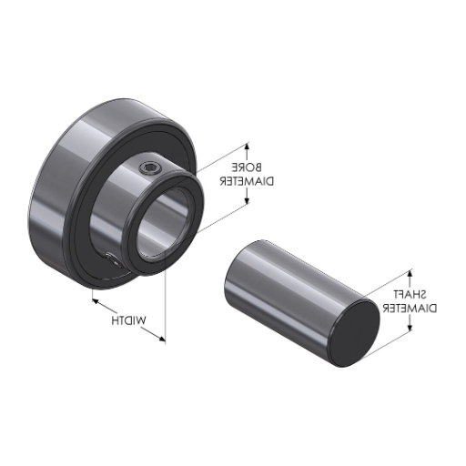
Bearing tolerance signifies the allowance in variation for the dimensions of a bearing during the manufacturing process. It is extremely crucial as it affects, for one, the fit, performance, and efficiency of the bearing in the mechanical system. Exact tolerances help to control alignment to avoid undue friction and more serious problems like excessive vibration or abnormal wear.
- Dimensional Accuracy: Mating interfaces of the bearing with its housing and shaft shall be fitted.
- Form Deviation: Helps keep uniform rotation and load balance.
- Running Accuracy: Minimizing vibrations to control misalignment.
The possibilities discussed are rational, since they cope with maintaining efficiency, prolonging durability, and minimizing cost overhauls in high demanding operations. The accuracy of all tolerances that are determined has their purpose which is based on operational conditions like speed, load, and temperature which in the end determines performance.
How tolerance affects bearing clearance and accuracy
Tolerance affects bearing clearance alongside accuracy by the fit of the parts and their behavior during operational loading, shifting, and temperature variations. To summarize, tighter tolerances usually diminish bearing clearance, which increases precision but requires careful thermal management to avoid excess preload. On the other hand, looser tolerances result in higher clearance, which is benevolent in terms of thermal expansion, but accuracy suffers.
- Radial Internal Clearance (RIC): Tightens RIC, increases operational stress while improving accuracy, and influences vibration levels and load distribution.
- Dimensional Accuracy (ISO tolerance grades): Guarantees high-speed or high-load applications due to sharp fit between the shaft, housing and bearing.
- Form Tolerances (cylindricity, roundness): improves durability and reliability through the enhancement of uniform load distribution across the bearing surface.
- Thermal Expansion Allowance: Mostly essential due to insufficient working clearance in high-heat surroundings.
Both bearing performance and durability depends on the appropriate selection of the operational factors such as rotational speed, load, bearing temperature and ensuring the idea conditions.
The relationship between tolerance and bearing lifespan
The connection between tolerance and a bearing’s lifespan is crucial and affects performance. Tolerance requirements guarantee that the bearing will function as intended within set, thus reducing abrasive damage and enhancing service life. For instance:
- Dimensional Tolerance: Bearings require effective radial and axial fits so that there is no excessive vibration or misalignment. Usual precision levels, like P5 or P4 from the ISO standards, are frequently chosen relative to the load and speed requirements of the application.
- Clearance Tolerance: The manipulation of internal clearances (C3 for warmer operating temperatures or normal for standard conditions) ensures proper lubrication and thermal expansion compensation.
- Surface Finish: Better surface roughness (Ra < 0.2 µm for races) leads to lower friction and wear, hence longevity under dynamic loads.
- Rotational Accuracy: Strict tolerances are often required for high-speed applications; for example, some runout must not exceed a few micrometers to maintain stability.
Setting these factors to the operational context allows the maximization of bearing lifespan while guaranteeing both efficiency and reliability.
How to read and interpret bearing tolerance tables?
Decoding Tolerance Class Designations
To decode tolerance class designations for bearings as fast as possible, I try to focus on their associated standards. These designations are related to international standards like ISO 492 and specify what the maximum allowable values for dimensions and angles of displacement are. Notable subclasses like P0 (Standard), P6, P5, P4, and P2 correspond to levels of accuracy and get tighter as the number decreases, with P2 depicting the highest accuracy level.
- Dimensional Accuracy: This includes allowances in bore diameter, outside diameter, and total length. An example would be in class P4, where bore diameter deviations are only a couple of micrometers. This leads to tighter fitting.
- Rotational Accuracy: Limits on runout values. For more demanding applications like P2, radial runout values may be less than 2 micrometers.
Through these tables I make sure that they selected tolerance class meets the required values regarding the performance of the application, whether it is high speed or certain load conditions. This guarantees that trustworthiness and operational efficiency is as per design.
Interpreting radial and axial runout tolerances
The effectiveness and precision of rotational parts like shafts, bearings, and housings rely heavily on radial and axial runout tolerances. Radial runout is the irregularity of a component’s surface relative to a circle rotating around a defined central axis, while axial runout is the degree of flatness or perpendicular measurement of a surface relative to the working rotational axis.
- Radial Runout (R): Tolerances are conventionally measured in micrometers, typically between 1 and 20 µm, according to the toleranced component class ( for instance,e bearing seats and precision spindles). Greater tolerances within the range are necessary for high-speed operations to minimize nerve-wracking vibration and noise.
- Axial Runout (A): these usually lie between 2 to 25 µm depending on how tightly operational needs, such as the alignment of couplings or gear assemblies, are specified. Tighter misaligned axis control and extravagant bearing wear demand accurate axial tolerances.
- Operational Rotational Speed: Denotes facilites runing at high RPM ranges. For these components, looser tolerances can be set without risk to dynamic stability, however they are required to minimize friction thermal effect.
- Load Capacity and Distribution: Runout could not exceed the values beyond which load distribution becomes uneven or concentrated over certain regions, accumulating stress and leading to fatigue failure.
Even small shifts in radial or axial tolerances may lead to internal mechanical imbalances, causing decreased operational efficiency, increased wear and tear, and possible extreme component failure.
What are the different bearing tolerance classes?
Overview of ISO tolerance classes for rolling bearings
The rolling bearings’ tolerance classifications are outlined by the international standards nominal ISO to guarantee the accuracy and dependability of bearings in numerous areas. To achieve optimal bearing performance for set operating conditions, these classes are defined to control important criteria like dimensional tolerance, running accuracy, and internal clearance. The tolerances articulated in ISO 492 are grouped in five overall divisions, which are ordered here from the least level of dimensioning to the finest level measurement:
- Normal (PN): Acceptable for sporadic use when there is an average level of precision accuracy. This class has tolerances which are in most instances difficult to achieve for the other categories.
- Class 6 (P6): For situations that require smooth operation and the greater dimensional and running accuracy, this class grants higher tolerances.
- Class 5 (P5): This class sets higher tolerances which is usually specified in high performance stability and efficiency machinery like high-speed spindles.
- Class 4 (P4): Very high precision aerospace, robotics, and precision instruments are designed to this class with the aim of ensuring higher tolerances and lower vibrations.
- Class 2 (P2): Used in advanced metrology systems where the highest possible tolerances are desired is this class.
Meticulously designed to an operational need, these tolerance classes set desired performance levels and guarantee the reliability and durability of bearings for a long time.
Comparing Class 0, Class 6X, and Class 5 tolerances
- Class 0 (P0): mark this for general-purpose operations without requiring high focus. Bearings that come within Class 0 tolerances are ideally suited for operations where moderate speeds and loads are experienced. This class has a more considerable allowance for dimensional deviation, which makes it more affordable, as the price is less precision-based systems makes it unsuitable for high-precision systems.
- Class 6X (P6X): This tolerence provides more accuracy than Class 0 but less than Class 5 and is, thus, intermediate. Mid-range automotive machine gearboxes are an example of using Class 6X tolerances set mid-range accuracy and low vibrations. The negative effects of moderately demanding conditions are mitigated by tightening the internal radial clearance and run out as compared to Class 0. So, they provide better performance and durability at the expense of looseness.
- Class 5 (P5): As the highest category, Class 5 bearings possess tolerances that are ideal for highly accurate applications such as machine tools, robotics, and manufacturing systems. The narrower tolerances both dimensionally and geometrically mitigate operational vibration and improve system stability. Factors such as axial runout and bore diameter deviation are controlled closely to meet the expected high-performance standards.
While all three classes serve specific operational purposes, the distinction among them will depend on the accuracy and application requirements needed.
Choosing the right tolerance class for your application
When choosing the best tolerance class, consider your application’s operational and mechanical as well as dimensional needs thoroughly. For example, tighter tolerance classes like IT5 or IT6 are recommended when high-speed performance or vibration reduction is paramount, as in aerospace or precision robotics. These classes have very small dimensional deviations, usually ±6 to 10 micrometers for mid-range components and drastically lesser performance deviations, ensuring alignment accuracy to a high degree.
However, for applications that do not make use of stringent performance requirements, such as generic machinery or structural components, tolerance classes like IT8 or IT9 may be enough. These classes have larger allowable deviations of approximately ±16 to 40 micrometers based on the nominal dimension but still ensure reliability to the device’s function and cost efficiency.
- Axial Runout: Higher tolerance classes usually limit axial runout beneath 10 micrometers and have high-precision applications.
- Finer surface finishes quantify greater precision, most often needing specified tolerances to the surface quality standards.
- Bore Diameter Deviation: For bore fits that are tighter, bore tolerance may need to be controlled within the boundaries of ±5-8 micrometers.
- Operational Environment: Dynamic or high-stress environments will need tighter limits due to factors such as thermal expansion or load variability ,which highly influence tolerance selection.
Aligning the technical specifications with the application requirements guarantees the performance, durability, and economy of the final design.
How to measure bearing tolerances accurately?

Tools and techniques for measuring bearing dimensions
Precision tools and accurate measurement techniques enable me to work within the specified tolerances to ensure that bearing dimensions are accurate.
- Micrometers: These tools are essential for measuring bore diameters and outer diameters, achieving accuracies of ±1 micrometer. These tools must be correctly calibrated to ensure optimum results.
- Dial Indicators: These measurements are critical for determining roundness and axial runout, in addition, these are necessary for dynamic applications with required tolerances in the 2-5 micrometer range.
- Coordinate Measuring Machines (CMM): These instruments offer detailed measurements for complex geometries with the guarantee that the determined tolerances will satisfy the high-precision needs (±2 micrometers at critical areas).
- Gauge Blocks: Used for the calibration of the measurement tool and verification of lower limit gauges. Particularly useful for the gauge inspection with tight ±5 micrometers tolerances.
- Surface Roughness Testers: Measures the quality of the finished surface with respect to the specified roughness average Ra parameters, in the case for bearings, usually between 0.1 and 0.4 micrometers.
All of these tools combined with the procedures of measurement I have set forth guarantee that the necessary dimensional and operational functional requirements for the bearing are achieved. For the optimal use of the bearing, its performance needs to be maximized.
Best practices for checking radial and axial runout
Every step of checking the radial and axial runout of any item needs to be done accurately and consistently because these factors are too closely associated with its bearing movement and bearing life. Here are some of the best practices you should follow:
- Employ Precision Measuring Equipment: A high-quality dial indicator, which can measure up to 1 micrometer, should be used to ensure that the deviation does not exceed this set pre-requisite so that the runout values are accurately measured. This will guarantee that runout values are accurately measured.
- Ensure Adequate Mounting: The bearing or particulary component being worked on should be mounted on a calibrated spindle or any other reference surface which is quite smooth and free from any kind of roughness. These ridiculously small parameter imposes a huge impact on the total measurement to be taken.
- Make Sure the Rotational Movement is Controlled: Whether it is manual or automated rotational movement, it has to remain constant. It is recommended that the movement requires a speed of 10- 20 RPM so that the changes can be captured without bringing additional shaking or disharmony into the system. This will also reduce the measurement vibration as well as instability.
- Capture Over A Range of Points: For radial runout, the measurements should be taken at intervals all round the circumference. For the axial runout, check the region proximal to the inner and outer edges of the edge face. Using this method guarantees high accuracy reliability of error detection.
- Check Against Criteria: Match the tolerances of the application with the runout values that were measured. As a general rule, radial runout for high-precision bearings will usually fall within the range of 1-5 micrometers and is quite flexible. Allowable axial runout tolerances usually reach up to 10 micrometers, which for the most part, is dependent on the load conditions expected.
Following these procedural steps ensures that I can identify gaps and take corrective action as necessary. It is this systematic approach that ensures operational reliability of the bearing.
What factors influence bearing tolerance selection?
Considering operating conditions and load requirements
When defining bearing tolerances, I emphasize several performance aspects of the application and load input. For example, consider the following:
- Rotational Speeds: With an increase in rotational speed, the amount of vibration and heat generated as a byproduct of operation also increases, which calls for tighter tolerances. Tolerances for applications above 10,000 RPM are generally expected to be P5 or P4 (ISO 492).
- Load Profiles: Axial or radial loading, especially with heavy loads, require reforged tolerances to avert failure and deformation of the part. For example, bearings with radial loads over 70% of dynamic load capacity should have minimal excessive radial clearances to ensure an optimal load.
- Temperature Changes: Clearances and fits on bearings can change due to thermal expansion. For applications with operating temperatures exceeding 120°C, stability can be lost, and tolerance ranges and materials may need extensive changes.
- Environmental Factors: Tighter tolerance levels and grades are required for contaminated or harsh environments sealed against debris and moisture.
These factors ensure the application demands are met with plausible tolerances, which boosts performance, reliability, and longevity.
Matching bearing tolerances with shaft and housing fits
- Shaft Fits: For rotating inner rings up to normal load conditions, an interference fit like transition fits H7/k6 or H7/m6 are best. In normal operation, with these types of fits, the bearing is well seated and has little chance of slipping with operational loads. A less tight fit, such as H7/,g6 may be appropriate for light loads or stationary inner rings.
- Housing Fits: Usually, the clearance fit of the housing for a stationary outer ring is nominal and can be H7 or better. However, higher speeds or more severe variable loads permit the use of tighter fits, like K7, to reduce vibrational misalignment due to looseness.
- Corrective Measures for Thermal Expansion: Where the temperature of operation has a significant positive effect on IRC (increased radius change), for example more than 120°C, this would need to be compensated for by changing tolerances or use of material with greater range of movement such as chrome steel which will maintain tolerances.
By these considerations with application conditions, I am reasonably sure that the matching tolerances to the shaft, housing, and bearings will provide the required work and reliability.
The impact of tolerance on bearing preload and clearance
By controlling the fit between the housing, bearing, and shaft, preload and tolerance dictate the influence of both axial and radial clearance. When tolerances are tighter, preload is increased, thereby increasing rigidity and rotational accuracy, however, too much preload may increase friction and result in faster wear. On the other hand, looser tolerances allow for greater clearance, which decreases friction but can also lead toa lack of stability or vibration while working under dynamic loads.
- Radial Clearance: For increased rapid rotation or thermal expansion, extra internal clearance like C3 or C4 is advised so that cyclic thermal expansion can occur with no functional issues.
- Preload Levels: Light preload is usually adequate for general machinery purposes, while applications that require more rigidity, like machine tools, will benefit from medium to heavy preloads.
- Shaft and Housing Fits: Tight k5 and m5 fits are known to provide high-speed consistent preload, but special consideration should be taken for circumferential thermal expansion as this would lead to excessive constraining of the bearing.
Choosing tolerances based on specific criteria allows me to achieve an optimized approach, which not only minimizes wear towards intended functionality but makes sure bearing performance is maintained throughout the application’s lifespan.
Frequently Asked Questions (FAQs)
Q: What are bearing tolerance tables, and why are they important?
A: Bearing tolerance tables provide information on the permissible deviations in dimensions and geometric accuracy for various bearing types, including ball bearings and tapered roller bearings. They are crucial for ensuring the proper fit, function, and performance of bearings in different applications. These tables help engineers and manufacturers standardize bearing dimensions and achieve the required precision for specific uses.
Q: How are diameter tolerances specified for ball bearings?
A: Diameter tolerances for ball bearings are typically specified for the inner ring (bore) and outer ring (outside diameter). These tolerances are given in mm and define the acceptable range of deviation from the nominal diameter. The tolerance classes are standardized according to ISO and JIS standards, with different classes offering varying levels of dimensional accuracy.
Q: What is radial runout, and how is it measured in bearings?
A: Radial runout refers to the deviation of a bearing’s outer or inner ring from a perfectly round shape when rotated in a single radial plane. It is measured as the difference between the largest and smallest measurements taken at various points around the circumference. Radial runout is an important factor in determining the precision and smoothness of a bearing operation.
Q: How do clearance classes affect bearing performance?
A: Clearance classes define the internal clearance or play within an assembled bearing. They are crucial for proper bearing function as they affect factors such as load distribution, heat generation, and bearing life. Different clearance classes are available to suit various operating conditions, with tighter clearances generally offering higher precision but potentially leading to excessive friction if not properly matched to the application.
Q: What are the key differences between metric and imperial bearing tolerance standards?
A: Metric bearing tolerances are typically specified according to ISO standards, while imperial bearings often follow ABEC (Annular Bearing Engineering Committee) standards. The main differences lie in the units of measurement (mm vs. inches) and the specific tolerance classes defined. However, many manufacturers provide tables that allow for easy conversion between metric and imperial tolerances to facilitate global use.
Q: How do width tolerances impact bearing installation and performance?
A: Width tolerances are critical for proper bearing installation and function, especially in applications where multiple bearings are used in sets. The ring width tolerance affects the overall width of the assembled bearing and can impact factors such as axial play and load distribution. Tight width tolerances are often required for precision applications or when multiple bearings need to work together in close alignment.
Q: What are accuracy classes in bearing tolerance tables, and how do they differ from clearance classes?
A: Accuracy classes in bearing tolerance tables define the level of dimensional and geometric precision of individual bearing components, such as inner and outer rings. They specify tolerances for factors like diameter variation, width variation, and runout. Clearance classes, on the other hand, relate to the internal clearance of the assembled bearing. While accuracy classes focus on component precision, clearance classes deal with the overall fit and play within the bearing.
Q: How do bearing tolerance tables help in selecting the right bearing for specific applications?
A: Bearing tolerance tables provide engineers and designers with crucial information to select bearings that meet the required precision and performance criteria for specific applications. By consulting these tables, they can choose the appropriate accuracy class, clearance class, and dimensional tolerances to ensure proper fit, smooth operation, and optimal load distribution. This helps in avoiding issues such as excessive friction, premature wear, or inadequate performance in the intended application.


UCTH213-40J-300 with Setscrew(inch)
CNSORDERNO: Normal-duty(2)
TOGN: UCTH213-40J-300
SDI: B-R1/8
SD: 2 1/2
UCTH212-39J-300 with Setscrew(inch)
CNSORDERNO: Normal-duty(2)
TOGN: UCTH212-39J-300
SDI: B-R1/8
SD: 2 7/16
UCTH212-38J-300 with Setscrew(inch)
CNSORDERNO: Normal-duty(2)
TOGN: UCTH212-38J-300
SDI: B-R1/8
SD: 2 3/8
UCTH212-36J-300 with Setscrew(inch)
CNSORDERNO: Normal-duty(2)
TOGN: UCTH212-36J-300
SDI: B-R1/8
SD: 2 1/4
UCTH211-35J-300 with Setscrew(inch)
CNSORDERNO: Normal-duty(2)
TOGN: UCTH211-35J-300
SDI: B-R1/8
SD: 2 3/16
UCTH211-34J-300 with Setscrew(inch)
CNSORDERNO: Normal-duty(2)
TOGN: UCTH211-34J-300
SDI: B-R1/8
SD: 2 1/8