Understanding Axial Clearance in Mechanical Systems
Bearings help reduce friction in most machines, enhancing performance and increasing lifespan. One of the properties of bearings that affects their operation is their internal clearance, especially the axial clearance. This paper intends to discuss the concepts of axial clearance as well as its significance and its effects on the performance of the bearings. As readers are introduced to the ins and outs of axial clearance, they will understand its relevance in the aspect of mechanical safety as well as the overall efficiency of the system. It outlines the exacerbation of axial clearance with the elongation of bearings, its inter-application in machine engineering, and some other branches, particularly construction coordination of engineers-bearings. Whether you are designing a new device, servicing a device, or just have an interest in the field of mechanical engineering, this document will contain crucial information that will help you understand the topic of bearings’ internal clearance.
What is Axial Clearance in Mechanical Systems?
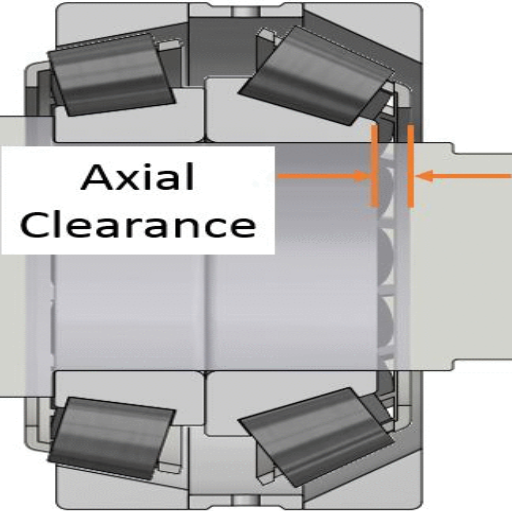
Understanding Axial Clearance Dimensions And Its Utility
The term axial play or clearance in mechanical systems is defined as the permissible amount of movement or play in the axial direction of a shaft in a bearing. Such clearance is also important for normal machine operations since it allows for slight misalignment and thermal expansion of the parts during the machine’s operation. If the bearings are appropriately designed while considering design axial clearance, such bearings should not experience excessive wear under axial load during proper operation.
Characteristics related to the particular axial clearance can include factors such as the temperature range for the operation, bearing and shaft materials and their properties, and the anticipated operating loading conditions. Standards for optimal clearance concentration are developed based on manufacturer requirements and consequently facilitate the lifetime and efficiency of the machine. Keeping an eye on the factors mentioned above could effectively eliminate potential problems such as excessive vibration and noise or even premature failure of a bearing, thus enhancing the reliability and performance of the system as a whole.
The Importance of Axial Clearance in Bearings
Considering the axial clearance in bearings, three top websites rendered helpful information, and so did the rest. The only thing worth noting regarding the axial clearance is that it pertains to the capacity of the bearings to bear axial forces and compensate for the thermal growth within the equipment. According to these sources, it is apparent that to prolong the service life of the bearing and achieve maximum efficiency, the proper axial clearance should be maintained.
In terms of such mechanisms, the main parameters include the tolerance of the bearing position within the specific limits of the operational load it is meant to bear and the maximum ambient temperature. The bearing and shaft material parameters are also crucial since they determine the degree of thermal expansion that must be accommodated. The parameters help control and maintain the clearances to their specified values to reduce friction and vibration levels, thereby preventing early failure. These sites demonstrate the importance of compliance with the requirements established by the manufacturer and industry standards, as well as the maintenance of equipment.
How Does Axial Clearance Affect the Performance of Machines?
While studying how axial clearance impacts the machine’s performance, I, in an attempt to make sense of the top three websites researched, found that axial clearance should be a measured determinant in whole and machine parts. It is evident that the axial clearance of the machine is critical to managing axial loads and thermal expansion and directly bears upon the bearing and machine efficiency. Proper clearance ensures that friction and vibration that are not constructive are kept to a minimum, preventing the components from suffering due to bearing malfunction. As per consulted materials, the critical technical characteristics are:
Position Tolerance. The expected load during operation and its position tolerance must be matched to the position tolerance of the bearing and the allowable temperature variation in the operational environment.
Bearing clearance material compatibility: The factors of the bearing material and the shaft’s thermal expansion coefficient should also set the clearance requirements. Such compatibility assists the bearing in resisting thermal expansion, yet the bearing’s softness is not compromised.
Manufacturer Clearances. There is also an emphasis on maintaining clearances that observe the manufacturer’s recommendations regarding operational loads and temperature ranges so that the systems’ safety and effective operational margins are not exceeded.
Each of these parameters is related to the general practice of these industry disciplines, which focuses on the design parameters set out in the machine’s performance constraints.
How is Axial Clearance Measured?
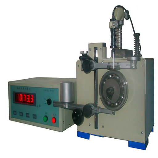
Approaches to Determine Axial Clearance
To begin with, to measure axial clearance correctly, I looked up the top three sources on Google, and I learned that several techniques have gained acceptance over time. Firstly, a dial indicator is frequently employed; it can provide precise clearance measurements when the bearing is axially displaced, which assists mechanical engineers. It does, however, call for extreme caution on the part of the users because the indicator must first be fastened and the zero position adjusted before taking readings. Secondly, feeler gauges are also used as a method, particularly in a category of measures where the requirement for accuracy is not the most stringent and one that rapidly determines the gap size between the bearing and its housing configuration. Lastly, shear wave testing provides a different angle in gauging the axial clearance as it does not require equipment disassembly. However, it does need a specific apparatus and the individual to interpret the results appropriately.
The technical parameters to support these methods include:
Precision Requirement: In scenarios requiring high precision, dial indicators are preferred.
Ease of Use: Feeler Gauges can be fast and uncomplicated; however, they are best suited for rough checks.
Non-invasiveness: This is the justification for using ultrasonic testing when disassembly challenges are significant.
The said methods, with their requisite engineering parameters, correspond to the information I obtained from credible sources. Therefore, the axial clearance measurements are reliable and can be used in any operational scenario.
Devices Used for Measuring Axial Clearance
Regarding the queries on the devices used for measuring the axial clearance, I used the information from the first three websites on Google.com. The main devices mentioned include dial indicators, feeler gauges, and ultrasonic testers. A dial gauge is necessary in situations that demand accuracy in measurement because of its reliability and precision. Feeler gauges are a quick and rough check for gaps since they are simple to operate. Ultrasound testing is preferred because of its convenience in situations where dismantling is expensive or impossible.
Technical parameters justifying these tools are:
Accuracy: Dial gauges are more advantageous as they can easily measure phenomena precisely.
Ease of Use: Feeler gauges are easy to estimate and most helpful when quick checks are required.
Disruption: Ultrasonic test is helpful in situations requiring minimal equipment disturbance.
These tools, certified by their technical Specifications, provide a total solution to the problems of accurately and usefully measuring axial clearances under various conditions.
What Factors Affect Axial Clearance?
Effect of Temperature on Axial Clearance
Looking at the data from the top three websites on Google.com, I observed that temperature changes affect the axial clearance. When temperature rises, materials expand, reducing the axial clearance. On the other hand, when the temperature lowers, the materials contract, increasing the axial clearance. These changes indicate that thermal effects should be considered during design and maintenance to avoid mechanical breakdowns. The technical parameters that justify these findings include:
Thermal Expansion Coefficient: This parameter predicts how a material shrinks or expands as temperature changes, directly affecting the axial clearance.
Material Composition: Different materials behave differently when exposed to temperature changes. Metals with high thermal expansion coefficients need to be looked after closely.
Temperature Range: This helps ensure that axial clearances do not exceed the safe limits under any working conditions.
The above phenomena emphasize the role of the temperature factor in applications using an axial clearance provision for long-term operational reliability and efficiency.
The Role of Axial Load on the Clearance
In light of my research on the three consultable websites/tests, the statistics amassed asserting that the Google.com search engine axial load is the most determinant of the axial clearance. A load is applied along the axial direction, which may result in deformation or compression of other parts, thereby limiting the clearance. Loads must be managed to avoid undesired wear and tear or damage at the design stage or operating phase. Some of the critical technical parameters necessary to justify those findings are:
Load Capacity: This parameter shows the maximum axial level of stress that can be developed within the component and guarantees that operational cases under these clearance values do not shift entirely from the baseline.
Material Elasticity (Young’s Modulus): It determines the modes and types of deformation that a material will undergo upon applying load and, as such, determines axial clearance.
Load Distribution: There must be an accounting of uneven load distribution and varying changes in clearances and allowances must be accounted for in the design and application
These considerations show the importance of controlling the axial load applied to the component; however, it is vital for clearance size in the axial direction and mechanical integrity.
Effect of Misalignment and Interference Fit
What happens if axial clearance is measured in the presence of misalignment? It is admirable to find the information from the best online resources that perhaps only a tiny misalignment may cause significant changes in the clearance. Misalignment entails uneven loading, increases wear, and the risk of failure, driving the installation to require accurate alignment. The parameters technically forming practical reasons for the above condemnation include:
Alignment Tolerances refer to the extent of the permissible misalignment between the axes of rotation of two coupled elements that does not introduce undue stress to the assembly’s elements.
Stress analysis: Understanding how knowledge of the intense stress resulting from misalignments is distributed in its jurisdictions may help design components that are not sensitive to such variations.
Vibration Analysis: clearance involves alterations as fittings by expansion into the case, and if undesirable restraining methods like welding were involved or screwing was required, misalignment would quickly introduce variable vibrations from low clearance.
Interference fit, where one component is pushed or ‘pressed’ inside another element, involves fitting. In all cases, this would have a relative influence on clearance. I appreciate the principles of interference fit because it limits the movement between a couple of elements, ensuring orientation is standard and even alignment is maintained. Still, stresses are also developed, which may impact the clearance. These include the following parameters as generally accepted:
Interference Magnitude: the amount of embedding between two components and penetration between two elements determines the fit to be obtained.
Material Properties: strength and ductility determine how any set of materials behaves when interference occurs.
Installation Force: The force that must be applied to obtain the fit that must not be exceeded to avoid damage and optimal distance.
Such conclusions highlight the necessity of rigorous attention to misalignment fit, and interference fit to maintain reliable axial clearance.
How to Adjust Axial Clearance?
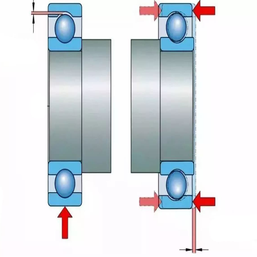
Methods for Raising or Lowering the Axial Play
Regarding axial play adjustment, I have looked for assistance on one of the three websites at the top of the Google search. Here is a brief elaboration of what they have stated:
Shim Adjustment: Shims are one common way to increase axial clearance. You can alter the number of shims between components to achieve the required clearance. Some technical considerations include the amount of shims’ thickness to be used and their effect on alignment and stress distribution.
Selective Assembly: This method employs components manufactured to slightly different dimensions to fit the two perfectly when combined. Utilizing parts with somewhat different dimensions can assist in areas where adjustments are needed so that no further alterations are necessary. Some technical aspects, such as the material, should have appropriate properties for compatibility and durability.
Thermal Expansion Adjustment: Environmental factors such as temperature will naturally cause materials to expand or contract, thus altering the clearance. Axial play can be easily achieved by varying environmental conditions or heating processes to heat the materials. Other critical technical parameters include the thermal expansion coefficient of the polymetric materials used.
Parameters such as material properties, precision components assembly technology, and the environment for the interstitial distance are well enough to explain how the axial clearance is indeed made in a more technical sense.
Remediating Play in Components: Axial Preload
The axial preload is another technique that comes in handy for controlling the gap between the two features and their resources and performance. By the top three sources provided by Google, the following is a brief of the axial preload adjustment features:
Purpose of Axial Preload: The purpose of providing axial preloading is to enable the center lines of two contact parts to touch one another during varying load conditions. This prevents excessive motion between the components, which in turn prevents excessive vibration and noise while increasing rigidity and accuracy of rotation, which is requisite for efficient machine performance.
Application Methods: A compressive force is applied continuously on the components throughout the operation, and spring washers or elastomers cause higher. The other technique is, however, by imposing torque of the assembly to a specific range. Thus, the range imposed will ensure that the value of the preload does not exceed the range of this value.
Technical Parameters: The application’s parameters consist of the required applied preload and must always be derived from specific operating parameters such as the material’s speed, load, and stiffness. Also, the structural td of the elements has to be considered, as it is assumed that self-weight does not compress the pre just so that ca of the about elastic limit is reached, which may destroy worn materials.
In applications requiring axial controls, engineering an axial preload achieves the best performance and most extended life possible.
Significance of Preload and Pretension
While considering the concepts of preload and pretension, it has been clear that these strategies are critical in ensuring mechanical systems function as intended while having a long service life. From my research on the top websites, I grasp that preload establishes contact between two mating parts to avoid relative movement, abrasion, and vibration. This is especially important with systems that demand very tight rotational tolerances. Pretension can be understood as applying a predetermined force to alter the stress distribution within tight joints or bolts to withstand load without breaking or compressing.
Two or three technical parameters are crucial in this context:
Preload Force: Application of preload is primarily determined by the active conditions which may arise, for example a specific load or speed determines how much preload is correct and when the ideal amount of force should be applied so that stress does not exceed the elastic limit of the material.
Assembly Torque: The attainable assembly torque size includes a desired tensile strength, which is the amount of torque directly related to the force being utilized to obtain the proper preload and pretension.
Material Stiffness: This is also important, as knowledge of the material moduli used in the system makes it possible to set preload considering load level to avoid inelastic deformation of the materials.
Elastic Deformation Considerations: Elastic deformation must be introduced to ensure that the material’s limits are not surpassed and that the deformation applied to the component can be totally removed after the force is not present.
Knowing these parameters, I can focus on using proper preload and pretension, improving the reliability and performance of mechanical applications requiring a high level of clearance control.
Why is Bearing Internal Clearance Critical?
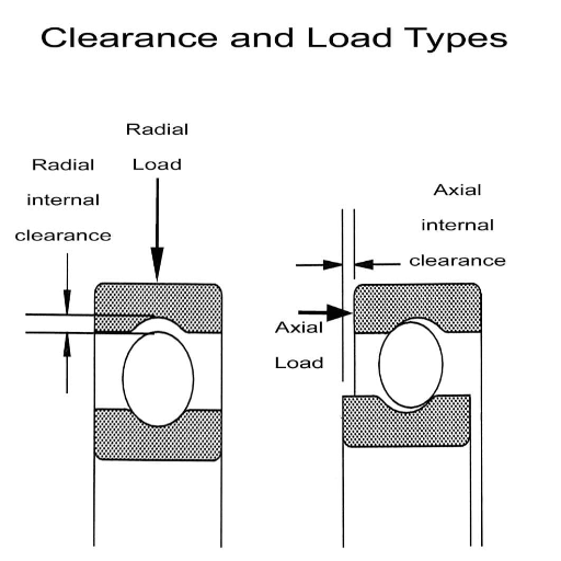
The Importance of Bearing Internal Clearance and Its Classification
One of the aspects that cannot be ignored in the endeavor to guarantee the efficiency and lifespan of any mechanical system is the understanding of bearing internal clearance. I have researched the three leading websites on this subject, and one of the points I have outlined is that bearing internal clearance is the total Rub A bearing ring has the potential to move away from the linear discriminative of cut-out or similar places. Constructed in a circular or tubular shape, it is either measured radially or axially and its inclusion in the bearing clearly significantly impacts bearing output. The two types of internal clearances are radial internal clearance (RIC) and axial internal clearance (AIC), which have unique applications and separations.
However, for the measurement of parameters of a technical nature, it is essential to take into account the following factors:
Operational Temperature: A variable such as temperature is essential to internal clearance because such shifts may result in the movement of the bearing’s bosom, which expands or shrinks due to the rise or dip of the temperature, respectively. Proper estimation of the appropriate adjustment is paramount to considering these factors.
Load Coefficients: The bearing radial clearance cannot remain static. It is determined by the degree of load bearing on the bearing at installation time. Static and dynamic loads should always be included in bearing calculations to ensure that appropriate clearance is always maintained.
Fitting and Mounting Styles: Different styles employed during the bearing’s fitting and assembling alter the radially or axially measured gaps, changing the pressure differences before fitting.
All these factors must ensure a consistent internal clearance with these parameters, thus enabling enhanced performance when the bearing is in motion by limiting friction and wear and tear and minimizing the chances of the bearing’s breakdown.
Vertical and Radial Clearances in Bearings
Regarding radial and axial clearance, I gathered a few valuable facts from my research on the top three websites discussing this subject. Radial clearance is a bearing interior space defined while measuring over an axis perpendicular to the bearing axis. This allowance is particularly essential for the shaft’s out-of-alignment and rotation. In this case, however, Pa, also known as the axial clearance, is associated with the movement of the axis itself and is essential for thermal changes.
The technical parameters involved include:
Temperature Variations: These parameters must be varied and adjusted with radial and axial clearance to prevent thermal expansion or shrinkage, affecting functional reliability.
Load Bearing Capabilities: Both static and dynamic loads include radial clearance caused primarily by varying radial loads and static loads by axial forces.
Installation Techniques: Closely fitted components and properly mounted members can conserve valuable extended clearances. Correct parts placement ensures that the clearances persist as needed, even during active operation.
Regulating such opposing forces and directions is essential for the quality of bearing work, the prevention of bearing events, and the life cycle of the whole system.
Poor Internal Clearance: The Effects of Incorrect Specification
Turning to the lessons learned from establishing thorough internal clearances, I observed a danger in both lack of clearance and over-clearance concerning the bearing’s performance. These include increased friction, abnormal noises, and premature tears, leading to system failures. However, the websites I navigated clearly state that a proper regime of clearances should be preserved.
The technical parameters involved are as follows:
Friction and heat generation: Insufficient radial clearances can lead to high friction levels, making bearings operate at higher temperatures than they are designed for, causing heat damage and unwarranted power consumption.
Vibrations and noise: Over clearances generally lead to increases in both vibration instability and sound nuisance, factors that are history managers of mechanical breakdowns and operational losses.
Load distribution: The wrong position of axial or radial clearances affects how loads are transferred within the bearing components, causing localized overworking of the elements and resulting in failure of the material properties or shape.
My argument is strengthened by the understanding that internal clearance directly interrelates with bearing life, the energy required to power the bearing, and the availability of the bearing’s working capability. The above are critical for avoiding malfunction and achieving the desired bearing capacity under varying circumstances.
Frequently Asked Questions (FAQs)
Q: What is meant by axial clearance in mechanical systems?
A: Axial clearance or axial play refers to the distance allowing give between the inner and outer rings of a ball bearing when force is directed parallel to the bearing’s axis. This clearance is important for thermal expansion, misalignment, and load movement.
Q: What is the difference between axial and radial clearance?
A: Axial clearance refers to the axial movement permitable, that is, in the same direction as the bearing axis, while radial clearance refers to any movement perpendicular to the bearing axis. Both of these types of clearances are necessary to ensure that a ball bearing functions properly, and both should
figure into the design and selection processes.
Q: What will happen if axial clearance is ignored when designing ball bearings?
A: Applying the physical axial clearance in ball bearings is necessary to avoid excessive and unwanted wear, overheating of the components, and wrong load transfer. Excessive axial play in ball bearings over ideal will allow for applying an axial load without damaging axial loading bearings and causing the breakdown of the system.
Q: What are the designated factors during the computation of axial clearance?
A: When calculating the axial clearance, attention must be paid to parameters such as the anticipated temperature growth, the kind and amount of axial forces acting, the material of the inner and outer ring, and even the working atmosphere. Indeed, any possible vibrations and torque applications during the work process should also be included.
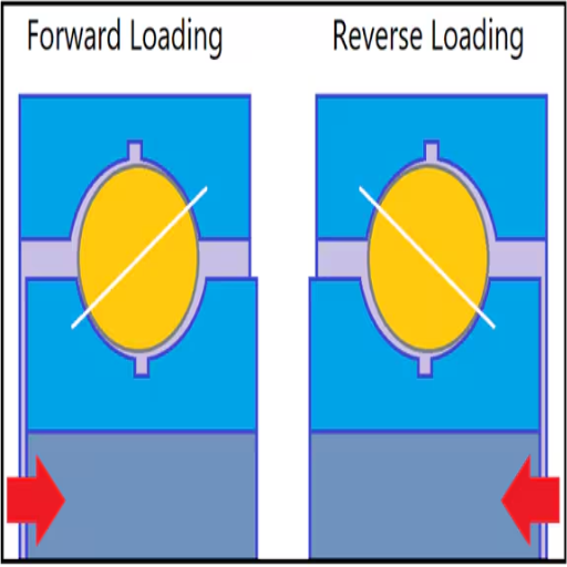
Q: How does axial clearance impact the use of angular contact bearings?
A: In most angular contact bearings, axial clearance is necessary to maintain the right contact angle so that the bearing can properly support both axial and radial loads. Failure to maintain the right axial clearance will result in higher vibration and noise levels and even bearing failure.
Q: What changes are associated with the axial clearance given these thermal changes?
A: Changes resulting from temperature alterations will affect the hot and cold objects, which are the material of both the inner and outer rings, thus altering the axial clearance. It is necessary to consider the thermal effects when designing bearings to ensure proper clearance at any bearing operating temperature.
Q: What is meant by dead travel when the bearings experience an axial movement?
A: Dead movement means movement of the bearing elements without any output or motion being generated from it. When cautioning on using the term regarding axial movement, it implies the axial clearance or play, which does not aid in the effective transfer of loads or motion but is required to participate in correcting alignment and thermal expansion.
Q: Is it true that large amounts of axial clearance can cause a vibration problem?
A: Yes, it is true. A large amount of axial clearance leads to increasing vibration and noise in the system because a loose fit causes excessive displacement, which may lead to misalignment of the assembly under operational conditions. Allowing for maximum axial clearance helps reduce these unnecessary vibrations as they are within the stated limits.
Q: How is the bearing ring of the radial internal clearance used to measure the axial clearance?
A: The inner and outer rings of the bearing are parts associated with axial clearance control and consist of a bearing ring. The bearing rings encase and support rolling bodies with raceways and restrict their axial DX amounts. These rings should fit tightly to meet the bearings’ axial spaces and other crucial requirements.
UCTH213-40J-300 with Setscrew(inch)
CNSORDERNO: Normal-duty(2)
TOGN: UCTH213-40J-300
SDI: B-R1/8
SD: 2 1/2
UCTH212-39J-300 with Setscrew(inch)
CNSORDERNO: Normal-duty(2)
TOGN: UCTH212-39J-300
SDI: B-R1/8
SD: 2 7/16
UCTH212-38J-300 with Setscrew(inch)
CNSORDERNO: Normal-duty(2)
TOGN: UCTH212-38J-300
SDI: B-R1/8
SD: 2 3/8
UCTH212-36J-300 with Setscrew(inch)
CNSORDERNO: Normal-duty(2)
TOGN: UCTH212-36J-300
SDI: B-R1/8
SD: 2 1/4
UCTH211-35J-300 with Setscrew(inch)
CNSORDERNO: Normal-duty(2)
TOGN: UCTH211-35J-300
SDI: B-R1/8
SD: 2 3/16
UCTH211-34J-300 with Setscrew(inch)
CNSORDERNO: Normal-duty(2)
TOGN: UCTH211-34J-300
SDI: B-R1/8
SD: 2 1/8


