


Understanding Cam and Follower Mechanism: How These Roller Mechanisms Transform Motion
The cam and follower mechanism is a fundamental component in mechanical engineering, widely utilized for its ability to convert rotary motion into linear or reciprocating motion. This intricate system plays a critical role in a variety of applications, from automotive engines to automated machinery, where precise motion control is essential. By employing a cam—a curved or profiled component—and a follower that tracks the cam’s surface, this mechanism ensures the accurate transfer of motion and force. This article aims to provide a comprehensive overview of how cam and follower mechanisms function, their key components, types, and practical applications, helping readers grasp the technical intricacies and the broader significance of this innovative engineering solution.
What are the different types of cams and followers used in mechanical systems?
Types of followers: knife-edge, roller, and flat-faced
- Knife-edge follower: This follower has a pointed edge that remains in contact with the cam surface. It is simple and compact while suffering from high wear and has high frictional forces due to low contact area. This design is favorable to low-load applications more concerned with accuracy rather than durability.
- Roller follower: This follower has a rolling element at the point of contact, and as such, it has less friction and greater durability than a knife-edge follower. This design is also more expensive and complex to manufacture. Roller followers work best under high loads or at high speeds.
- Flat-faced follower: This follower uses a flat cam surface, and the follower has a larger area of surface contact, therefore reducing wear and permitting greater loads. These followers are widely employed in mechanisms where smooth motion is needed.
Each type of follower is specially designed to accomplish certain performance metrics, therefore providing various solutions for the requirements presented in a mechanical system.
Motion patterns: translating follower vs oscillating follower
The translation and oscillation patterns of each follower type are fundamentally predetermined by the follower’s geometry and type of movement in which the follower engages in a cam-follower system. A translating follower executes a linear motion in the direction of the cam profile and the accompanying follower action. Such a motion occurs, for example, in systems with linear motion, such as engine valve systems. The more critical features for a translating follower are linear displacement, velocity, and acceleration, which are all dependent on the cam profile and the speed of its rotation.
In contrast, an oscillating follower performs a circular motion about a fixed axis of rotation. This follower is applicable in systems which utilize oscillatory motion such as some packaging machines or printers. Primary technical factors of oscillating followers are angular displacement, angular velocity, and the radius from the pivot point to the contact points of the cam, which defines the transmitted force and torque.
Every mechanism consists of specific motion types, so the analysis concerning the output motion needed, load conditions, and the wear-resistance required is what defines the design consideration.
What are the common applications of cam and follower mechanisms?
Cam and follower in internal combustion engines and camshafts
Cams and followers devices have crucial importance in the workings of an internal combustion engine, especially in the movement and timing control of the engine valves. Each cam rotating the camshaft is attached to a camshaft as if it goes by the crankshaft rotation. Such rotation is transformed to be the movement of the follower, which pulls up or pushes down the spring-loaded valves to control the air-fuel mixture flow in and exhaust gases out.
- Cam Profile Design: The cam profile angle determines the motion of the follower and all connected components, which includes follower acceleration, speed, and displacement. Examples of common profiles are tangent cams or arc-circular cams.
- Lift (Valve Travel Distance): This dimension indicates the maximum height of the opened valve and is usually expressed in inches or millimeters.
- Timing Angle: The angle of displacement at which the cam makes the follower perform the task of a valve opening or closing is called the timing angle. This needs to be accurately placed in coordination with engine cycles.
- Material and Wear Resistance: The aforementioned devices may require to be made of hardened steels or alloy materials since high temperatures, pressures, and cyclic mechanical strain shall be too high even for forged steels.
- Follower type: Roller followers are widely used in fast-moving engines to minimize friction, while flat-faced followers are typically used for Diesel engines or big stationary engines where strength is the major consideration.
These technical aspects are important for proper operation and functionality of the engine. A properly constructed cam and follower system enhances the power output of the engine while reducing the possibility of damage, noise, power consumption, and other forms of waste. The integration of all these parts allows for sophisticated mechanical timing determination which is the core of modern engine design.
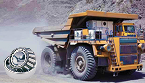
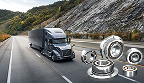
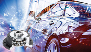
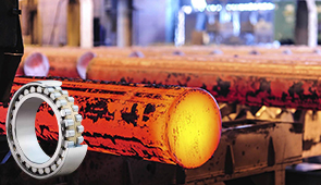
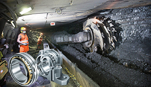
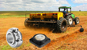
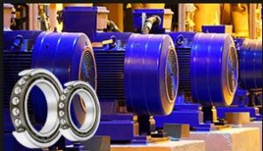
Industrial applications of cam follower bearings
Cam follower bearings are dominantly used in industries because they can handle heavy loading, difference in speeds, and can function effectively under difficult conditions. Such bearings are often found in machinery for packaging, modern belt systems, and even robots for the assembly of various products that need movement and strength. Moreover, these bearings are important in machinery used for handling items and even during production for textiles as they offer efficient operations continually.
- Load Capacity: Like other bearings, their efficiency is dependent on maintaining heavy radial and thrust loads. Their dynamic load capacity ranges between 3,000 and 50,000 N and is determined by the size and design of the bearings.
- Speed Performance: With favorable lubrication, the set rotational speeds can exceed 3,000 RPM, which ensures compatibility with high-speed industrial systems.
- Material Composition: Hardened steel or stainless steel are the main components due to their high resistance to wearing and corrosion, which is crucial in such high demanding environments.
- Sealing Mechanism: The further advancement allows the use of superior seals that retain lubricant and prevent contamination which serves to improve service life in harsh operational deficits.
- Operating Temperature: Effective within wide limit of temperatures ranging between -30°C to +120°C which will suit various industrial environments.
The characteristics emphasize the functionality and adaptability of cam follower bearings throughout different industries reinforcing reliable motion control and maintenance free operation over time.
Everyday devices where cam and follower mechanisms are used
The functionality of many devices we use daily revolves around the use of cam and follower mechanisms that achieve superior motion control. Such mechanisms are common in:
- Automobile Engines: Cams and followers are used to limit the opening and closing of intake and exhaust valves, operating alongside the engine.
- Printing Machines: these mechanisms are put in place in order to control the movement of rollers and print heads, achieving higher speed and accuracy in print production.
- Sewing Machines: A rotating cam transforms the rotational motion into a linear oscillating motion, driving the needle and thread hook mechanisms. In this case, smooth material operation is required, along with material durability, to reduce maintenance needs.
- Automated Vending Machines: Systems with outside access employ a cam mechanism to allow dispensing items in a controlled manner. Such designs have size restrictions defined by low noise and dependability of activation cycles.
- Clocks and Watches: Apart from timekeeping, cams are employed to serve other functions, including the striking mechanism.
In all cases, proper material selection, surface treatment, and lubrication is critical to achieving optimal performance and wear characteristics for the cam and follower systems.
How is the motion of the follower determined by the cam profile?
Relationship between cam profile and follower motion
The follower, without any exception, is governed in its motion by the cam profile, which determines displacement, velocity, and acceleration of the follower. How the motion of the follower cam is achieved is called the follower cam, which transforms rotation into oscillatory or translational motion of a particular magnitude.
- Base Circle Radius: It is the lower rim of the cam profile which is considered to define the least displacement of the follower and enables motion.
- Lift: This is the maximum height or range of movement given to the follower, so it is determined by the cam lobe shape.
- Profile Slope: This defines the smoothness of motion achieved while the given displacement is produced and is essential towards offsetting the spindle vibrations and the wear of the cam, the follower.
- Speed of Rotation: This alters the dynamic reaction forces which are defined in the follower employed and calls for concern at high speeds, for trouble attention has need up to the material properties and lubrication used will result in high stress and excessive damage.
- Follower Type: The active motion must be flat faced, roller or mushroom, in accord the cam must ne designed to ensure the one motionless contact which reduces frictiontion.
Every one of these factors has to be well designed to provide the needed follower movement while balancing the overall system reliability, efficiency, and life.
How the shape of the cam controls the required motion of the follower
Cam design features that directly influence profile velocity and follower motions. While describing the specific follower motions, I would break them down into these major details: displacement, velocity, profile acceleration, and lift.
- Cam Profile Geometry: The shape of the cam face markedly determines the movements of the follower. For example, a pear-shaped cam often produces a gradual rise motion followed by a fall, while heart shaped cam revolves smoothly and uniformly throughout the cycle. If the profile is not set accurately, sudden and excessive shifts may occur which can be harmful.
- The Lift (Rise) and Fall (Return): The height of the rise and the downturn are inherent in the contour shape of the cam. Any failure either in the lift or the fall would automatically cause inefficiencies in the system.
- Cam Velocity Diagram: The charted values of speed in every period of the cam’s rotation must fit the mechanical needs. Sharp changes in velocity often correlate to high stresses, so a cam designed with a smooth velocity curve ensures durability.
- Acceleration Control: The cam must guarantee that well-distributed acceleration or deceleration phases are maintained. Any sudden changes in acceleration are avoided because they create higher forces which would damage both follower and cam over time.
Concentrating on these factors during design and optimization processes enables the cam to effectively manage the follower’s motion in accordance with the performance requirements established by the system.
What are the advantages and disadvantages of using cam and follower mechanisms?
Benefits of the cam follower mechanism in mechanical systems
First, these mechanisms can control motion with high accuracy, which is desirable for tasks that require highly precise timing, as in internal combustion engines or automated production machinery. Additionally, the cam profile can be designed to achieve distinct motion paths—constant velocity, acceleration, or rest—which is beneficial when optimizing performance.
Also, cam and follower mechanical systems are strong and can withstand different operational load levels. Factors such as cam material strength, surface hardness, and lubrication require careful consideration to reduce wear and ensure reliability. For instance, hardened steel is a common selection due to its ability to endure high-contact stress cam and follower interfaces.
Finally, cam mechanisms greatly simplify and improve the compactness of the design. Rather than achieving optimal output from complex mechanisms, they can achieve efficient output from simple mechanisms at a lower volume. This feature makes them essential in applications with limited space. Their alignment, manufacturing tolerances, and dynamic balance justify their efficiency and effectiveness in modern mechanical systems.
Limitations and challenges of cam and follower designs
Although the cam and follower mechanism has innumerable advantages, multiple drawbacks and issues still need to be dealt with for the design and practical use of the equipment. One drawback is that with constant engagement of the cam follower, there is a wear and tear factor associated with it. Because of this, material loss takes place over a period, which may affect the accuracy and time duration the system can operate. To combat wear, factors like the material’s characteristics, surface treatment, and the lubrication used all need to be tightly controlled.
Another challenge in the equipment design and usability comes from accurately controllable inductive manufacturing tolerances. Tolerances for the cam profile, which is usually in the range of microns, have a direct relation to the motion of the follower, which means that super-precise end machining operations are necessary, which are very expensive. There are also dynamic stability problems at higher operational speeds because of the unbalanced forces and vibrations, which is dangerous because the system can become unstable. There are also restrictions on the speed since high-speed operation may cause problems with follower bounce or follower chatter; this necessitates the careful evaluation of spring stiffness and damping ratios.
Finally, cam and follower systems are limited in their ability to deal with very high loads. This restriction requires the use of high-yield strength materials and the incorporation of sophisticated coatings to alleviate stresses and improve lifetime. These problems underscore the need for complex design considerations to ensure that the mechanisms function reliably and efficiently within their intended contexts.
Comparing cam mechanisms to other motion transfer systems
Cam mechanisms differ from other systems that transfer motion, such as gears, linkages, or belts, in various critical ways. First, cam and follower mechanisms are particularly useful for producing sophisticated and irregular motion patterns, which would be difficult or impossible with the aid of belts or gears. This benefit is due to configurable custom cam profiles, which enable required motion designs. On the other hand, gears with fixed tooth ratios are preferable in cases where continuous rotational motion speed is needed.
Regarding efficiency, cam systems suffer more friction losses because of cam-follower sliding contact, as opposed to the rolling contact of a gear or tensile driven contact of a belt. This results in increased wear and a potential decrease in system life. For example, the system life or efficiency of cam systems tend to be affected by the coefficient of friction ranging from 0.05 to 0.15 for lubricated metal on metal contact and surface finish of the cam profile.
The other difference is the load capacity. Cams, for example, with a good choice of material and stress patterns, can take on moderate loads. However, gears are better for transferring high torques. This is due to their larger contact areas. For instance, spur gears have material-dependent contact pressure limits of 1,200 MPa. Cam systems, on the other hand, often need advanced coatings or surface treatments to deal with such high stresses.
Lastly, cam mechanisms usually have greater manufacturing complexity because they require precise machining for profile generation. Standard gear teeth or belt configurations are relatively easier to produce in bulk. Therefore, like most designs, the choice between these systems usually depends on a target application such as motion complexity, efficiency, load capacity, and economical factors.
How to select the right cam follower bearings for specific applications?
Important considerations for cam follower bearing selection
The process of selecting cam follower bearings involves operational analysis as well as the matching of technical details. The following factors are of utmost importance:
- Load Capacity: Determine the static and dynamic loads that are expected. In answer to those loads, bearings with appropriate and adequate load ratings in Newtons or pounds should be selected. These bearings recommend safety and durability while operational.
- Operational Speed: Evaluate the speed needed for rotation or linear movements. Check if the operative speed rated in RPM of the bearing does not result to overheating or undue wear.
- Material and Coating: Evaluate the conditions of the environment. For externally corroding places or extreme temperatures, stainless steel or corrosion resistant coatings are most appropriate.
- Precision and Alignment: Consider if the bearings help to accommodate misalignment or deflection in the system. Crowned rollers designed in some bearings can accommodate these situations.
- Lubrication Requirements: Make determinations on the maintenance capabilities. Self-lubricated designs can eliminate frequent grease applications in difficult and highly active areas.
- Mounting Type: Examine how the cam follower will be mounted about the stud type or yoke type models, depending on the space available or gthe eometry of the application.
- Temperature Range: Confirm the range of operating temperature expected on the bearing performance. For example -20F to 250F would keep the bearing functioning under strenuous situations.
- Shock and Vibration Absorption: For high-impact or vibration environments, choose bearings that feature hardened raceways and maximized damping features.
Synchronizing these factors with the needs of the application guarantees better effectiveness, lesser degradation, and longer functioning life.
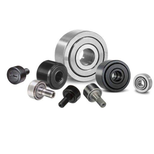
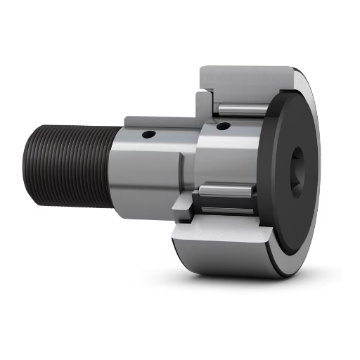
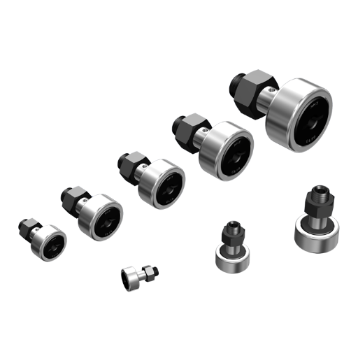
Types of cam follower bearings and their specific uses
Each type of cam follower bearing addresses a particular kind of application and operating environment. As such, I will shortly explain the different types of cam followers, their applications, and some essential technical specifications.
- Standard Cam Followers: Typical cam followers are designed to sustain moderate loads and speeds; as such, they are most frequently used for conveyor systems, material handling systems, and other linear motion devices. Their basic load-carrying structural needle roller pattern assures load bearing over the entire surface. Normal working conditions would include a radial load of about 1,000 to 10,000 pounds, which is dependent on the follower’s dimensions and contour.
- Heavy Duty followers Cam: These followers with enhanced features such as bigger needle rollers are specially designed for heavier duty applications. Because of their robust designs, these can withstand excessive loads of more than 10,000 pounds. Typical application areas include construction machinery, mining equipment and heavy machines prone to shock loading.
- Eccentric Cam Followers: This cams design has an off-center shaft which alteration of position of the follower in relation to the surface interacting with the track. These types of cam followers are perfect for offsetting alignment issues for assembly lines and printers. With the external eccentric, the normal allowance for eccentricity is generally 0.040 inches.
- Crowned Cam Followers: In areas with track misalignments or misalignment deflections, the edge stress is reduced by using these with a crowned outer surface. Their common application is in textile machinery or packaging lines. They geometrically minimize wear and ensure even smooth operation over time, despite minor misalignments.
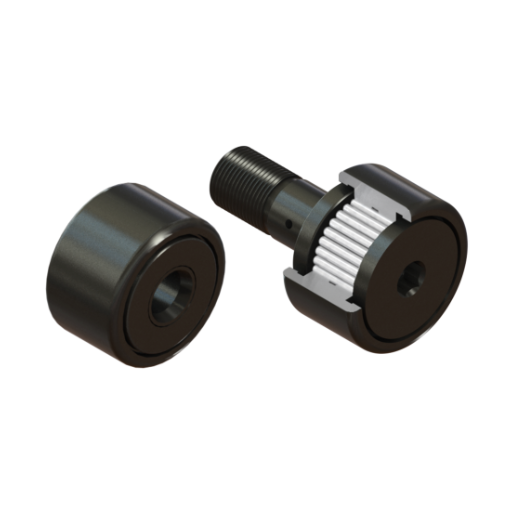
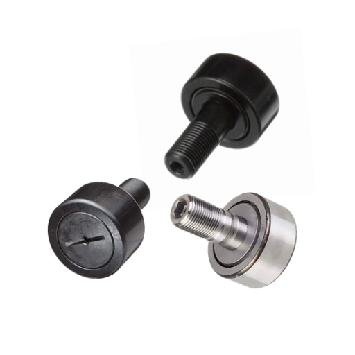
- Stud-Type and Yoke-Type Cam Followers: Stud-type cam followers are suited for automated machinery with space constraints, as they are directly mounted via their threaded stud into the application. Yoke-type cam followers are installed on a shaft, making them more suitable for higher dynamic loads, but yoke-types are generally superior to stud-types in radial load capacity by about 25%. All yoke types are more durable.
This specific design of each type by functionality means that the type of system can be tailored to the type of follower needed for optimal functionality. To ensure accurate selection, factors like load capacity, speed, operating environment, and dimensional limitations must be evaluated.
Frequently Asked Questions (FAQs)
Q: What is the working principle of the cam and follower mechanism?
A: The working principle of a cam-and-follower mechanism centers on motion transformation. A cam is a rotating element with an irregular shape that, through its rotation, causes the follower to move in a predetermined path. As the cam rotates, its profile comes in contact with the follower, which then moves according to the contoured surface of the cam. This mechanism effectively converts the rotary motion of the cam into reciprocating, oscillating, or irregular motion of the follower. The design of the cam profile directly determines the type of motion and displacement pattern that the follower experiences during operation.
Q: What are the main types of cams and followers used in mechanical systems?
A: There are several types of cams and followers used in mechanical systems. Cams can be classified as disc or plate cams, cylindrical cams, translating cams, and globoidal cams based on their shape. Followers are categorized by their motion (translating or oscillating), surface shape (knife-edge, flat-faced, or roller), and method of constraint (pre-loaded or gravity). Roller cam followers are particularly common because they reduce friction and wear. The specific type of cam and follower selected depends on the application requirements, where the follower may need to perform linear reciprocation, oscillation, or a combination of movements based on how the cam moves during operation.
Q: How does the profile of the cam affect the follower movement?
A: The profile of the cam directly determines how the follower moves during operation. Different cam profiles generate different follower motion patterns—uniform, modified uniform, harmonic, or cycloidal motion. The shape of the profile dictates whether the follower reciprocates, oscillates, or follows another predefined path. Sharp corners or sudden changes in the cam profile can cause jerky follower motion and increased vibration, while smooth profiles provide more gradual acceleration and deceleration. Engineers carefully design cam profiles to ensure the follower motion meets specific requirements for timing, speed, acceleration, and displacement while minimizing mechanical stress and wear on both the cam and the follower.
Q: What are the advantages of using a roller follower in a cam mechanism?
A: Using a roller follower in a cam mechanism offers several advantages. First, the rolling contact significantly reduces friction between the cam and the follower compared to sliding contact, which improves efficiency and reduces heat generation. This lower friction also minimizes wear on the surface of the cam, extending the mechanism’s operational life. Roller followers distribute contact forces over a larger area, reducing stress concentrations and preventing premature failure. They can handle higher loads and speeds more effectively than flat or knife-edge followers. Additionally, the direction of the follower movement is more predictable with roller followers, making them ideal for precise applications where consistent motion patterns are required.
Q: Where are cam and follower mechanisms commonly used in applications?
A: Cam and follower mechanisms are used in applications across numerous industries. In automotive engines, they control valve timing and operation. Industrial machinery utilizes them for automated assembly lines and packaging equipment where precise, repetitive movements are needed. Textile machinery employs cam mechanisms for thread handling and fabric manipulation. In printing presses, cams control paper feed and impression timing. Consumer products like mechanical watches and toys often incorporate small cam mechanisms. Medical equipment may use cams for precise instrument movement. These mechanisms are particularly valuable in applications requiring predictable, programmed motion patterns or where electronic control systems would be impractical or overly complex.
Q: How does a cylindrical cam differ from other types of cams?
A: A cylindrical cam, unlike the more common disc cam, has its working profile cut on the surface of a cylinder. The follower moves parallel to the axis of rotation of the cam rather than perpendicular to it. This design allows for the translation of motion in a direction parallel to the cam’s rotational axis. Cylindrical cams can provide more complex motion patterns and often allow for more compact designs in certain applications. They typically have grooves cut into the cylindrical surface, with the follower riding in these grooves. This configuration is particularly useful when space constraints exist in the radial direction, but more room is available along the axis. Cylindrical cams are often used in textile machinery, automatic screw machines, and certain types of engine timing systems.
Q: What happens when the follower has a flat surface versus when it’s a roller type?
A: When the follower has a flat surface, it makes line contact with the cam, distributing forces over a wider area but creating sliding friction that can cause wear and efficiency loss. Flat followers are simpler and less expensive but require careful lubrication and material selection to manage the sliding contact. In contrast, roller-type cam followers create point or rolling contact with the cam surface, significantly reducing friction and wear. The rolling action converts sliding friction to rolling friction, which is more efficient and generates less heat. However, roller followers are more complex, require bearings, and create higher contact stresses due to the smaller contact area. The choice between flat and roller followers depends on factors such as speed, load requirements, precision needs, and cost constraints in the specific application.
Q: How do you ensure proper contact between the cam and the follower during operation?
A: Ensuring proper contact between the cam and the follower requires several design considerations. Most importantly, a spring-loaded follower is typically used to maintain constant contact with the cam surface, preventing separation during high-speed operation or when the follower must move against gravity. The spring force must be carefully calculated—strong enough to maintain contact but not so strong as to cause excessive wear. Proper lubrication is essential to reduce friction and wear at the contact point. The materials of both components must be selected for compatible hardness and wear characteristics. Precise manufacturing tolerances are critical to ensure the cam profile matches the design specifications. Regular maintenance, including inspection for wear, proper lubrication, and spring tension adjustment, helps maintain optimal contact throughout the mechanism’s operational life.

UCTH213-40J-300 with Setscrew(inch)
CNSORDERNO: Normal-duty(2)
TOGN: UCTH213-40J-300
SDI: B-R1/8
SD: 2 1/2
UCTH212-39J-300 with Setscrew(inch)
CNSORDERNO: Normal-duty(2)
TOGN: UCTH212-39J-300
SDI: B-R1/8
SD: 2 7/16
UCTH212-38J-300 with Setscrew(inch)
CNSORDERNO: Normal-duty(2)
TOGN: UCTH212-38J-300
SDI: B-R1/8
SD: 2 3/8
UCTH212-36J-300 with Setscrew(inch)
CNSORDERNO: Normal-duty(2)
TOGN: UCTH212-36J-300
SDI: B-R1/8
SD: 2 1/4
UCTH211-35J-300 with Setscrew(inch)
CNSORDERNO: Normal-duty(2)
TOGN: UCTH211-35J-300
SDI: B-R1/8
SD: 2 3/16
UCTH211-34J-300 with Setscrew(inch)
CNSORDERNO: Normal-duty(2)
TOGN: UCTH211-34J-300
SDI: B-R1/8
SD: 2 1/8