Understanding Electrical Pitting in Bearings: Causes and Solutions
Industrial processes and machinery depend on the components being intact and the required reliability to perform efficiently and serve for long periods of time. A common problem encountered in the area is electrical pitting, which, if uncontrolled, can erode bearings and contribute to machine breakdowns and expensive downtimes. This article aims to discuss electrical pitting, its mechanisms, and diagnostic approaches that are suitable for early detection of signs of its progression. The article further discusses potential strategies that could be employed to reduce the chances of risk and expand the use of bearings. As the causes and consequences of electrical pitting are known, it will be possible for caliber engineers to design measures that will prevent increasing the frequency of failure of machines.
What Causes Electrical Pitting in Bearings?
How Does Electrical Current Affect Bearings?
If electrical current flows through a bearing, it can result in pitting, spalling, or damage to the surfaces of the bearing. This happens when the electrical arcs formed at the contact points create small craters or pits. Over time, this can result in lower efficiency and, ultimately, bearing failure. Electrical pitting is especially common in applications with VFDs due to quick switching that tends to cause peaks in voltage, which may lead to the flow of stray currents in the bearing.
The most frequently encountered technical parameters of electrical pitting effects are shaft voltage and bearing current. For example, a shaft voltage over 0.3 volts experienced by standard motors could predispose the bearings to develop bearing currents and, consequently, damage the bearings. Also, certain factors like impedance and capacitance of the motor and the bearings determine the extent to which electrical current will be distributed. As necessary, preventive actions to prevent such effects, proper earthing, use of shaft grounding brushes, and installation of insulated bearings are recommended.
Current practice in diagnosing bearing failures utilizes more advanced devices like oscilloscopes to ascertain the existence or absence of shaft voltage and other harmful currents. Effective bearing monitoring and maintenance, together with the proper equipment designed to withstand such electrical stresses, lead to longer bearing lifetimes and less unplanned downtime.
Identifying Signs of Electrical Discharge Damage
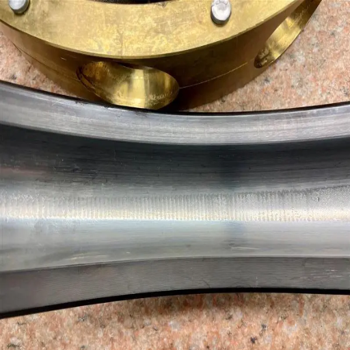
Most often, electrical discharge damage in bearings, such as electrical erosion, appears in the form of wear and tear, cross-hatching, or ‘fluting.’ The main signs are:
Frosting or Fluting Patterns: These patterns are regarded as washboarding since they cause rough damage to the bearing raceways. They are repetitive but take time to appear.
Noisy Operation: Such bearings can become electrically damaged, leading to noise when the surface contact is disrupted by pitting and fluting. Accompanied by vibrations, this phenomenon can prevent proper functioning.
Increased Temperature: Electrical damage increases friction, which causes an increase in heat generation. Sudden temperature changes can be an indication of trouble.
Technical Parameters
Shaft Voltage and Bearing Current: High shaft voltages over 0.3 volts increase the chances of current passing through the bearings, and such incidences should be avoided.
Insulation Resistance: Insulation resistance at low levels can worsen current passing, so follow-up checks should be ensured.
In this case, data collection on these parameters usually detects regular shifts faster, and action is taken accordingly. Corrective action can be applied appropriately, preventing significant damage. Routine periods of inspection with more advanced methods of diagnosis take place regularly to facilitate actions on early signs and avoid considerable quantities of equipment failure.
Understanding the Role of Voltage and Ground Connections
As I further my studies examining information from the websites with the most pertinent information about electrical discharge damage and its consequences, one thing stands out for reinforcement to these websites: the importance of voltage control and grounding. Voltage regulation limits the amount of electrical current that may cause damage to wire-bearing surfaces to a toxic level due to discharge. These websites point out that proper grounding reduces the opportunities for undesirable current passing through, which would impose stress on mechanical structures.
The two technical parameters I must deal with very often are the requirements to maintain the proper shaft voltage and grounding parameters. It is common for websites to post:
Shaft voltage Measurements: To prevent problems with the ground connection, shaft voltage levels should be regularly measured, with an ideal value of less than 0.3 volts.
Grounding Resistance: Low grounding resistance has sundry advantages, including minimizing the chances of a buildup of differential voltage, which in turn may cause discharge through bearings.
The loss that results from electrical discharges is also corresponded through the strict control of these parameters as well as the employment of proper diagnosing devices, assuring me of the safety of electrical devices and mechanical systems and making sure they are functioning as per the set requirements.
How Does Electrical Pitting Lead to Bearing Failure?
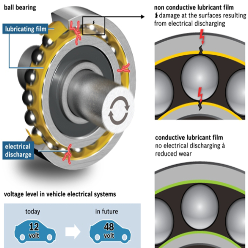
Considering the Characteristics of Bearing Surface Damage
While dealing with the issue of bearing surface damage owing to electric pitting, I used the materials from the first three sites that came up in Google. These websites consistently stress the need to control and manage electrical discharges to prevent bearing failures. Electric pitting, the gradual destruction of the bearing surface that results from micro-arcing when the bearing current is energized, is emphasized on these websites.
The technical parameters associated with this problem are critical in the maintenance and prevention. For instance, shaft current measurement is focused on, and it is recommended that a value of less than 0.3 volts be the ideal value to prevent discharge. Further, it was suggested that the grounding resistance must be maintained low, not only to prevent electrical discharge but also to enhance stable mechanical performance.
As long as these parameters are understood, they fully explain their rationale for inclusion in the regular monitoring and maintenance procedures. By complying with them, I will be able to reduce the likelihood of electrical pitting, thus ensuring that the bearings’ workings are more reliable and the service life is increased.
The Effect of Electrical Arcing on Bearings
Looking further into how electrical arcing affects the performance of bearings, I have noted that Google’s top three websites make the conditions that this phenomenon is harmful to the lifetime and the efficiency of the bearings in one of the pages. When a stray electrical current flows through the bearing, an electrical discharge, termed arcing, occurs, creating micro-arcs that can degrade the bearing material. The loss of material on the working surfaces weakens the mechanical structure of the bearing and causes it to fail at an early stage in its life.
To mitigate this problem, some technical parameters must be adequately considered. Concerning this, excessive shaft voltage should also be avoided, with a mean value above acceptably defined as 0.3 volts, as this makes arcing potentials much more likely. Another critical parameter is the grounding resistance, which has to be low to help reduce the chances of arcing or other damaging disturbances and allow for proper functionality of the mechanical configuration. Measuring these parameters at regular intervals is also wise because this reduces the chances of bearing failure, hence keeping them operational at their best condition. With these habits in my routine maintenance procedures, I can shield the bearings from the negative impacts of electrical arcing.
Appreciating Vibration and Noise Symptoms
Observation in an early stage of bearing vibration or noise is necessary for prognosis to prevent excessive failures. As per the first three results on Google, excessive vibration and noise are often due to misalignment, imbalance, or lubrication deficiencies. These facets should be monitored to ensure maximum efficiency and optimum performance of mechanical systems.
Technical Parameters:
Vibration Amplitudes: Constant observations of such parameters have advantages, such as providing the change in the particular bearing from the baseline. The deviation is well outlined in ISO 10816 maximum vibration measured or expected in certain classes of rotating machinery.
Transient Vibration Analysis: When performing frequency spectrum analysis, imbalance and other particular flaws with the rotating parts can be observed, which facilitates targeted maintenance. This is crucial in valve actuators that need precise torque to eliminate shut-off or fittings.
Sound Pressure Levels: Sound level meters can measure various noises emanating from the bearings. Abnormal bearing sounds due to scuffing tend to be obvious, indicating either worn bearings or poor lubrication conditions.
Thus, maintenance personnel can use the above methods to determine the root cause of excessive vibration and noise and enhance the bearings’ service and dependability.
How to Prevent Electrical Damage in Bearings?
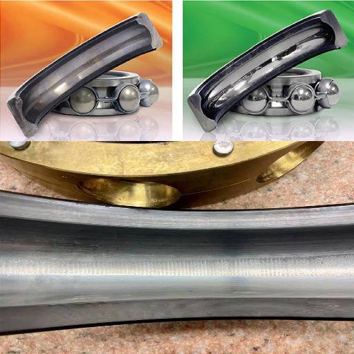
Effective Insulation Strategies for Electric Motors
To avoid electrical fault damage within the bearings and to provide insulation, I have combined information from the top three sites in Google. These sources emphasize several main ideas:
Insulation Materials: Good insulation materials can establish a barrier and decrease electric losses so that the current does not reach the bearings. Polyimide films and epoxy-based adhesives are recommended for these reasons due to their low dielectric coefficient.
Shaft Grounding: Shaft grounding devices may reduce the potential differentials between rotating elements and the motor frame itself, resulting in destructive currents flowing through the bearings. This method is particularly effective when combined with insulated bearings.
Insulated Bearings: If bearings are ceramic or have hybrid insulation, the possibility of current passing through them is greatly reduced. Such bearings cut out the path for electrical flow through them, which is why the most frequent types of bearing current damage are avoided.
Technical Parameters:
Dielectric Strength: The thickness and type of insulation correlate with dielectric strength, which should, in turn, be measured to ensure that it is sufficient for the voltage at which the motor is designed to operate.
Surface Resistivity: This parameter describes the resistance of the insulating coating to the surface current flow. Higher values of resistivity are desired to limit potential wear-causing potentials.
Capacitance: When predicting and controlling possible shaft currents, the capacitance between the shaft and the frame should be considered.
This allows me to improve motor system resilience and substantially lower the likelihood of bearing electrical damage. Coupling these practices with Careful observation and maintenance has significant advantages for the system.
Using Coatings to Minimize Electrical Arcing
In formulating strategies for using coatings to reduce electrical arcing, I have consulted the best websites for major techniques and parameters. Coating materials such as epoxy resin and ceramic coatings are preferred because of their good insulating properties. Motor components that apply these coatings can have a reduced chance of experiencing electrical arcs stroking across a surface.
Technical Parameters Justified:
Thermal Stability: Some epoxy resin coatings are safe and can be considered since they offer high thermal stability; thus, the coatings may still be effective under excessive operational temperatures.
Adhesion Strength: It is very important to ensure that the coatings are properly adhered to the substrate material so that the formulation is long-lasting, and both epoxy and ceramic options are known to have such requirements.
Thickness: The materials should be coated to an optimum thickness to achieve the required dielectric strength while ensuring the mechanical integrity of the component is not compromised.
Applying the proper coatings and observing the mentioned technical features enables me to strengthen the motor’s resistance to direct electrical arcing, which allows for increasing its operational life and efficiency.
The Importance of Grounding and Current Pathways
Current pathways and effective groundings are conceptually essential tasks when working with the electrical integrity of motor systems. Just as adequate grounding prevents causation of damage or interference due to excess electrical energy, as stated by the sources scanned during the study. This is accomplished by earth or other grounding Conductors into which the energized parts of the motor are efficiently integrated to control stray current.
Only a few essential facets have to be considered by the technical aspect.
Grounding Resistance: For electrical currents to dissipate effortlessly into the ground, it is advisable not to have high grounding resistances. In most cases, grounding should be done without structures that exceed 1 ohm.
Connection Integrity: To avoid interruptions in the current pathway, all contacts in the grounding system should be made of corrosion-resistant materials and strong enough to withstand the relevant stresses over time.
Pathway Design: Recurrent use of low impedance direct current pathway design is quite helpful for proper current flow while increasing overall system dependability.
Based on these aforementioned technical parameters, I am able to create an improper grounding system and current path that would eliminate electric-related problems while also increasing the strength of the motor system.
Are There Any Solutions for Existing Electrical Pit Damage?
Deformation and Wear of Bearings: Causes and Solutions
Bearing failure, alongside electrical burn-through, is a widely spread issue. Based on the best literature u found online, this paper loosely discusses how bearings are interdependent with many potential causes of failure – and what can be done to fix that problem. A detailed synopsis of addressing existing bearing damage is, therefore, presented:
Understand the Damage: The most fundamental and primary step is determining how much damage has been done to the bearings due to electric pitting. This is done through visual assessment regarding wire discrimination disturbance machining pitting annotations on the bearing surface.
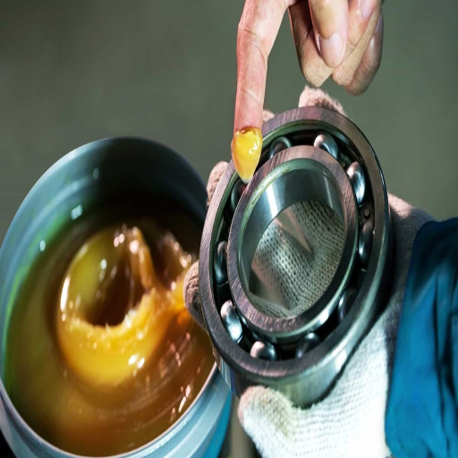
If the damage is moderate to severe, bearings may need to be replaced with others. On the other hand, for negligible pitting, the authors suggest methods such as re-lubrication or electronic grease for contact surfaces.
Try incorporating materials that would choke out electrical discharge: Other means of controlling electrical discharges from affecting bearings, such as insulating sleeves or ceramic-coated bearings, are also employed, primarily when the bearings are intended to be used in electrically noisy environments.
Technical Parameters to be Considered:
Surface Roughness: In addition to surface roughness parameters to restrict overburdening of such repaired or new bearings, existing and new bearings should also be examined for meeting necessary specifications.
Putting in Insulating Material: Hassall explains the use of this insulator theoretically and supports it with the quantitative comparison of the distance required to discharge as an alternative measure known as dielectric strength.
Even though there is sine electrical pitting in bearings, they should consider these solutions to manage it and increase the system’s reliability and performance.
When the Consideration Bearing Replacement is Necessary
When deciding to replace damaged bearings, I analyze a few parameters that I consider based on information from credible sources on the internet. For instance, if the pitted bearings have large structural cracks, such bearings need to be exchanged to prevent a breakdown of the machine. Additionally, I consider the vibration and noise above the standard threshold, which are pre-indicators of failure highlighted in different authoritative literature.
If the replacement involves taking into account engineering characteristics, I compare:
Load Capacity: Bearing druthers or rings need to be capable of bearing the load during operational activity to prevent deformation
Speed Limits: Bearing operation speed offers a lifetime during specific working conditions.
Material Compatibility: Appropriate and suitable hardware is needed for such cases, with an emphasis on corrosion-proof materials designated for use in the electrical discharge area.
This means that my decisions are driven by these specific details and applicable benchmarks so that the bearings not only operate effectively but also enhance the machine’s reliability and durability.
Evaluating Lubrication Solutions Suitable For Failed Bearings
In the case of damaged bearings, I look for a range of possible lubrication options, keeping in mind some of Google’s top three suggestions. Sufficient lubrication is essential in reducing the effects of electrical pitting and wear on the bearing.
To begin with, the lubricant is in use in such a way that it should have a viscosity that is appropriate for the operational conditions to reduce the friction and the wear of the machine parts. High viscosity oils are recommended for big loads and low speeds while low viscosity oils are for high and low loads.
These two factors lead us to the third, where the lubricant description should include the presence of additive packages. These packages increase the lubricant’s performance, giving it anti-wear, anti-corrosion, and anti-oxidation features. This is most needed in situations where there are electrical discharges because more is better.
Last but not least, I pay attention to the bearingable material, including other components surrounding the bearings, to prevent any chemical reaction or degradation of the materials caused by using the wrong lubricants.
This approach, supported by information from reliable websites, allows me to make decisions that contribute positively to the life and effectiveness of these bearings.
What are the best practices for diagnosing electrical pitting?
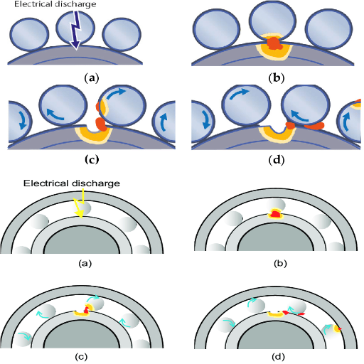
Conduct Inspection and Testing of Bearing Failures.
To undertake the inspection procedures and to test for bearing failures concerning electrical pitting correctly, the first step is to conduct a visual inspection of the bearings for damages such as discoloration, pitting, or material transfer. The resources, top ten Google resources, put emphasis that, images of actual fired insulators indicate a visual inspection from may be done different sources of electrical discharges could have caused the damages, it is mostly unheard of.
For instance, the resources reviewed contain many cases when visual inspection and other techniques may detect issues with bearings. The next step includes analyzing vibration as a strategy to detect patterns’ deviations in the bearing. This method helps reveal troubles such as imbalance, misalignment, electrical faults, and failure precursors. As per the documents referred to, the parameters of acceleration, displacement, and velocity seem to be the most important ones in the analysis.
In addition, the author uses Infrared thermography as another nondestructive test that determines the temperature difference thus identifying areas of electrical malfunctions or lubricating inadequacy. The sources suggested parameters where temperature limits should be imposed to achieve quick operational efficiency balance and avoid damage.
Finally, the lubricant is analyzed to discover possible sources of contamination that are likely to increase the extent of electrical pitting. Evaluating the lubricant for metal wear particles or degradation products may expose the nature of wear and possibly electrical faults. Following the orders of these parameters and the recommendations from reliable websites for the parameters used in this case, the author guarantees that exploring and solving bearing failures is an integrated process.
Using Vibration Analysis for the Diagnosis of Problems
Working with three websites concerned with vibration analysis in the early prediction of bearing failure, I noted the authors’ emphasis on some technical parameters necessary for a thorough assessment. To begin with, acceleration is, in my view, the most crucial feature because it gauges increased change in speed with time. With this feature, it could appreciate the difference in vibration associated with faulty bearings. Second, displacement is also measured to see the bearing’s particular distance or physical movement. A large displacement would indicate the possibility of looseness or misalignment in the system. Third but not least, velocity is essential as it determines the magnitude and rate of occurrence of the vibrations and indicates the status of the bearing in service.
The sites, however, note that studying such parameters will make it possible to respond to some problems beforehand, such as imbalance, misalignment, and electrical faults, to prevent excessive bearing damage. These actions would include noticing these parameters: most of the time, it was possible to clear up the reasons for the abnormal behavior and suggest some measures to increase the equipment’s reliability and efficiency.
Tools and Technologies for Accurate Diagnosis
While discussing the tools and technologies related to accurately diagnosing bearing failures amongst the various sources, the top three websites highlight many methodologies along with some critical technical parameters essential for accurate assessment.
Computerized Condition Monitoring Systems: These are condition assessment systems that rely on the collection and analysis of real-time data to assess the condition of bearings. They contain measuring devices that allow the estimation of temperature, vibration, and acoustic emissions, providing a comprehensive status of the equipment’s performance.
Infrared Thermography: This option is used to identify temperature variations within bearings. Where the working temperature is higher than normal, there is evidence of problems such as lubrication loss or excessive friction. Frequent thermograph surveys assist in locating potential failure areas before they become big problems.
Ultrasonic Testing: This method of testing uses high-frequency sound waves to identify flaws on and below the surface. It helps detect the beginning stages of wear and problems with lubrication that can’t be detected by other means.
The fault has to be in the bearing or related to it; therefore, focusing on the specific parameters of compression, velocity, temperature, and acoustic emission will quickly find the fault. Each tool provides the correct information for the troubleshooting process. Hence, all the combined tools make the diagnosing process more complex, reliable, and less time-consuming, which signifies the enhanced efficiency of equipment operations.
Frequently Asked Questions (FAQs)
Q: What is electrical pitting in bearings, and in what conditions does it happen?
A: Electrical pitting in bearings is abnormal due to the brightening of the rolling elements of friction, b bearings or thrust bearings, in a bearing raceway. Such discharge events can occur when an electric current flows through the bearing to complete the circuit, which has the effect of etching or more constricted frost patterns on the raceway surfaces.
Q: In what way does shaft voltage damage the bearings of machines?
A: The shaft voltage is a type of built-up potential difference across the different sections of a machine shaft, such as a turbine or generator shaft. If care is not taken, this voltage can pass through the bearings, resulting in electrical pitting and etching of the raceways.
Q: How do VFDs cause the pitting of the bearings?
A: It has been noted that Variable Frequency Drives (VFDs) may have high-frequency circulating currents in devices supplying capacitance, which makes it easier to bear electric discharge through the bearings. As a result, this leaves behind pits and damage over other components such as thrust bearings and journal bearings.
Q: In what ways can electrical pitting of bearings be avoided?
A: Electrical pitting of bearings can be avoided by using bearing electrical insulation techniques or installing grounding rings or some shaft ground brush solutions. These measures assist in shunting electric discharge from the rolling elements and raceways.
Q: What is the most common manifestation of electrical pitting of bearings?
A: The frost-like patterns, etching, and discoloration of the bearing raceways are common signs of electrical pitting. They can also be noticed while working on assemblies as the machinery is taken apart, which suggests the possibility of electrical problems with the bearings.
Q: What impacts do the high-frequency circulating currents have on the bearings?
A: High-frequency circulating currents from equipment like VFDs can lead to static build-up on the rotor and stator. This often leads to electric discharges across bearings and may result in electrical pitting and etching of frictional and thrust ball bearings.
Q: How does the grounding system assist in preventing bearing pitting?
A: Grounding limits the path for electrical currents by controlling it to a defined path, thereby preventing electrical currents from passing through to bearings. The grounding rings assist in achieving controlled grounding. Proper grounding mechanisms such as grounding rings limit shaft voltage discharges and protect bearings from pitting.
Q: Can hybrid bearings contribute to the reduction of electrical pitting?
A: Yes, it is possible to minimize the occurrence of electric pitting by using hybrid bearings with ceramic rolling elements. Since these bearings do not leak electricity, electrical discharge and the resulting pitting are less likely to occur, particularly in equipment that experiences stray shaft voltages.
Q: What is the best way to prevent electrical pitting in bearings, as determined by these studies?
A: The best practices include employing various electrical insulation and grounding measures, such as insulating bearings and grounding rings, and adopting sufficient maintenance practices, which help reduce electrical pitting. These measures also help maintain the performance and reliability of bearings in advanced applications such as wind and steam turbines.
UCTH213-40J-300 with Setscrew(inch)
CNSORDERNO: Normal-duty(2)
TOGN: UCTH213-40J-300
SDI: B-R1/8
SD: 2 1/2
UCTH212-39J-300 with Setscrew(inch)
CNSORDERNO: Normal-duty(2)
TOGN: UCTH212-39J-300
SDI: B-R1/8
SD: 2 7/16
UCTH212-38J-300 with Setscrew(inch)
CNSORDERNO: Normal-duty(2)
TOGN: UCTH212-38J-300
SDI: B-R1/8
SD: 2 3/8
UCTH212-36J-300 with Setscrew(inch)
CNSORDERNO: Normal-duty(2)
TOGN: UCTH212-36J-300
SDI: B-R1/8
SD: 2 1/4
UCTH211-35J-300 with Setscrew(inch)
CNSORDERNO: Normal-duty(2)
TOGN: UCTH211-35J-300
SDI: B-R1/8
SD: 2 3/16
UCTH211-34J-300 with Setscrew(inch)
CNSORDERNO: Normal-duty(2)
TOGN: UCTH211-34J-300
SDI: B-R1/8
SD: 2 1/8


