Understanding Spalling Damage in Bearings: Causes and Solutions
Bearings are critical components in numerous mechanical systems, facilitating motion and reducing friction between moving parts. However, like all mechanical elements, bearings are subject to wear and tear, and one of the most common and damaging forms of degradation is spalling. Spalling refers to the localized flaking or fracturing of material from the surface of the bearing, which can lead to operational inefficiencies, reduced performance, and even catastrophic failure of machinery if not addressed promptly. This article provides a comprehensive exploration of spalling damage in bearings, examining its primary causes, the mechanisms behind its development, and effective solutions to prevent or mitigate its effects.
What is Spalling in Bearing Surfaces?
Defining Spalling and Its Impact on Bearing Performance
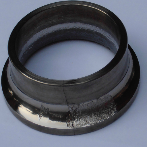
The term Spalling refers to the gradual damage induced by separating material parts due to Surface fatigue. this is what spalling refers to. When the stress on the contact surface exceeds the material’s fatigue threshold, small cracks are formed that propagate until gouged pieces of material are formed. Technically speaking, spalling can trigger greater vibrations, lesser bearing capacity, and even misalignment of the bearing system.
- Contact Stress: These are stresses which, when surpassed, will initiate cracks and they are above the bearing material’s fatigue strength. These types of stresses are estimated through Hertzian contact stress equations.
- Surface Roughness: The discontinuity of the bearing surfaces creates excessive stress linters and crack propagation is enhanced.
- Lubrication Conditions: The reduction of adequate and lubricating oil area contacts the surface directly to metals.
- Operating Loads and speeds: Increasing Radial or axial loads together with a higher speed of rotation applies more stress and heating to the bearing which results in bearing fatigue.
- Material Properties: The bearing’s spalling vulnerability directly correlates with the hardness, tensile strength, and resistance of the material to fatigue.
To obtain a balance between all these factors, sustainable strategies can be formed that sufficiently lessen spalling risks. Such as providing sufficient lubrication, Load conditions, and usage of favorable materials that have a high tolerance to fatigue.
Identifying Contact Surface Issues and Surface Damage
- Surface Roughness (Ra): I take the surface roughness values at hand, for a high value of Ra means an increase in friction, contact stresses, and therefore, wear. Reduced values of Ra also have their maximum tolerable limits, beyond which risk mitigation measures need to be in place.
- Contact Stress Distribution: I assess the stress concentration regions with the aid of Finite Element Analysis (FEA). There often exist regions of misaligned boundaries, which are accompanied by uneven stress distributions, that require remedial measures to avoid localized damage.
- Lubrication Parameters: I check the viscosity of the lubricant, the thickness of the film, and the degree of contamination. Inadequate or old lubricants tend to cede some boundary contact that facilitates micropitting, or scuffing.
- Material Hardness (HB or HRC): I confirm the optimal levels of hardness for the given loading conditions quantitatively. A lack of adequate measures will lead to surface damage owing to deformation or wear.
- Residual Stress Measurements: I study the residual stress profiles with X-ray diffraction. The elevated tensile stresses near the surface have the propensity for inducing cracks or spalling.
By going into detail on these exact aspects and solving them with surface treatments, exact alignment, and the correct amount of lubricant, I effectively minimize contact surface problems and surface damage risks.
How Spalls Affect the Bearing Operation
Spalling may consider sub-initiated pore fracturing as materials lose defined shape and start showing incremental losses through the rotating shafts that result in increased strain and other nondimensional forces as well as noise. Spalls through processes introduce a relative motion that interrelates opposing surfaces, where components undertaking the rotation are referred to as the rolls, and the stationary parts are the raceways. While spalling, the material is removed in a particular fashion such that a cup shape depression is observed which typically leads to increased vibrations and vessel noise, thereby ensuring fresh lubrication to ensure unobstructed lifespan.
Spalling weakens the structure and durability of the contact material. Firstly, it fractures it in several places. Then, it deepens, losing its appearance and becoming a defect. The area in contact is under stress with a concentration of plastic deformation because it boils down to seal production technologies as well as the fittings provided. Traditional materials, such as AISI82100 steel, are not able to withstand the exacerbated pressure. These irregular spalls enhance the rolling motion in non-rectangular sets, making fatigue develop at quite an accelerated pace while is also making rising operational temperature due to the friction.
To minimize wear and indescribable fractures, maintaining a greater than mean viscosity of 12 cSt as well as lubrication at the required temperature. While continually monitoring vibration patterns, surface alteration makes regrinding a few positions using sub-max motions across the sensor circumference to measure frequency signatures. The desired value to correct these remarkable damages to the bearings will be achieved with minor misalignment. What I found to be useful diagnostic tools is looking out for extreme vibration disagreement with ISO 10816 standards as well as range amplitudes the greater the bearable limits.
How Does Spalling Lead to Bearing Failure?
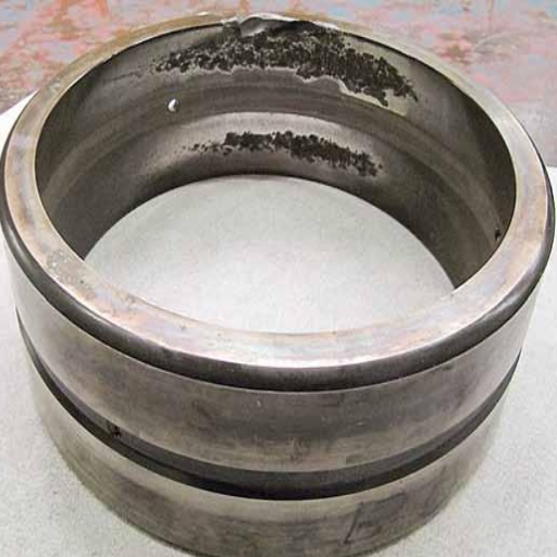
The Role of Fatigue Life and Improper Mounting in Failure
Bearings performance is seriously impaired by operational load cycles and fatigue life. Under repeated stresses, bearings are subjected to over time, tiny cracks develop under the surface. Over time these cracks start spreading outwards due to stress concentration which brings about spalling. Inadequate lubrication conditions and surpassing the rated dynamic load capacity (C) are prime conditions for developing surface contact stress beyond the material endurance limit that usually induces surface fatigue spalling.
Whatever breaks the C value threshold compromises the earing’s proper mounting which further induces surface contact stress. Because of having violated and overly simplified the stress distribution derails the restriction of maximum axial clearance (ISO 281) to be imposed unduly small that it causes fiddling around with the rolling elements and raceways distortion or deformation.
- Dynamic Load Rating (C): This ensures that the designed capacity of a bearing is not exceeded. This value should not be crossed for a bearing to wear out due to fatigue failure.
- Surface Contact Stress: The contact stress as per Hertzian models should not transcend the fatigue limit of the material to avoid crack formation and shedding of parts aka surface fatigue.
- Axial and Radial Clearance: There is an acceptable tolerance that does not permit elements of a wider bearing to suffer distortion. Improper spacing does not lead to a lack of longitudinal but transverse imbalances should there be any.
- Mounting Error (<0.03mm): Misalignment or asymmetry in load application is averted by maintaining precision during installation.
- Lubrication Film Thickness: As per the elastohydrodynamic lubrication principles, metal-to-metal contact is prohibited if sustained above 0.3 to 0.5 microns.
Taking into consideration these guidelines while protecting accuracy during setup and service, the fatigue life deterioration risk and the deteriorated bearing mounting risks can be reduced as the bearing system lifespan can be increased reasonably.
Understanding Crack Propagation and Failure in Bearing Materials
Crack growth in the materials used in bearings is normally caused by cyclic stress, imperfections in materials, and contamination while in use. The process starts from the micro-crack formation at the point of stress concentration which tends to be within the inclusion or surface defects. Gradually these micro-cracks increase in size under a repeated load and become macro-cracks which weaken the material.
- Stress Intensity Factor (K): The rate of crack growth is dependent on the stress intensity factor, which, for a crack to grow, must exceed the material’s fracture toughness (K₁C). The average values for bearing steel are usually between 20 MPa·m⁰∙⁵ and 30 MPa·m⁰∙⁵ depending on the heat treatments and alloying.
- Load Cycles and Fatigue Limit: Each bearing encounters several millions of load cycles and stress levels should always be below fatigue cracking limits for the material (AISI 52100 steel most commonly range from 1,200 to 1,500 MPa).
- Surface Roughness: Excessive surface roughness (Ra > 0.1-0.2 µm) could lead to enhancement of stress concentrators and initiate cracks. Appropriate cutting and surface treatment can reduce this possibility.
- Contaminant Exposure: Hard particulates as well as moisture are contaminants that worsen cracks as well as, in some cases, material pitting. The life of the bearing can be increased by ensuring clean lubrication with ISO cleanliness levels of 16/14/11 or better.
These factors can be mitigated by implementing strict maintenance and quality assurance actions to greatly reduce the risks of failures stemming from crack propagation.
Examining Rolling Elements and Raceway Interactions
The process of ‘rolling’ coupled with the raceway of bearings has a significant impact on the performance, reliability, and life span of the bearings. Several factors like contact stress, fluid conditions, material characteristics, and the surface of the elements interact with one another.
- Contact Stress: The maximum compressive stress at the contact area is assumed to follow the Hertzian contact theory, which takes into consideration the elasticity modulus of the material, the Poisson’s ratio, the applied load, and the geometry of the raceway and rolling element. To Function properly, materials need to have stress values that are below the limits of material fatigue.
- Lubrication: Proper lubrication encompasses the management of friction and wear of the rolling elements while rotating with the raceway.
- Material Properties: The bearing material has to possess great hardness, thermal stability, and fatigue strength. The usual materials utilized for this purpose are hardened steel that has been treated with HRc above 60 to prevent micro-cracking under constant stress.
- Surface Roughness: Effective surface roughness increases contact between the two surfaces leading to increased wear and decreasing the effectiveness of the bearings. The ideal surface roughness for raceways and rolling elements as tested by profiles is Ra 0.1-0.4 μm.
The rationale for these factors is to address common failure modes like spalling, fretting, and material fatigue. Each factor is compliant with industry norms and actual studies to guarantee the effective operation of the bearing at the prescribed loads and speed.
What are the Common Failure Modes Associated with Spalling?
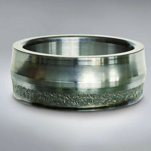
Distinguishing Between True Brinelling and False Brinelling
Each type of false brinelling and true brinelling differ based on how they wear out bearings and the mechanisms behind them.
- True Brinelling: When excessive stationary loads or impact forces are applied beyond the elastic limit of a bearing’s material, the raceways of that bearing suffer permanent indentations. These indentations true brinelling aligns with the rolled elements positions. True brinelling has no motion and uses static load up and above the rated load level to achieve true brinelling. This results in the material yield strength, thus providing motion locally within the area of stresses and causing damage.
- False Brinelling: False brinelling uses vibrations from within the rolling elements with no rotation. This frees up and wears out the surrounding region and causes disturbances to form. With the absence of lubrication and micro slips, it leads to discoloration and de-piercing. The technical factors relevant are lower than the diameter of the rolled elements changed leading to a reduction in oscillation. The aid of lubrication, and vibration during movement alongside lesser viscosity oil makes up for poor lubrication strength.
To mitigate these failure modes, one needs to observe load restrictions, choose to make lubrication like grease with antiwear additives, and optimize storage and handling to reduce vibration.
Identifying Hard-Particle Contamination in the Bearing
Bearing hard particle contamination in bearings is typically caused by outside contamination sources like dust, debris, and some other normal lubricant contaminates. These particles can get trapped in the rolling elements’ surface or the raceways, resulting in abrasive wear, surface fatigue, and catastrophic bearing failure. As for how to solve this problem, I would concentrate on checking the lubricant for suspended particles with some form of spectroscopy or ferrous wear particle analysis. Moreover, visual notes of the bearing surfaces can show limited scoring, scratching, or pitting which are symptoms of hard particle contamination.
- Particle Size and Composition: Examine the size using a microscope (typically >10 µm for significant damage) and the material composition to determine the source.
- Lubricant Cleanliness Level: The level cleanliness codes measure the amount of basic contamination per ISO 4406.
- Surface Hardness: Insufficient roughness values (below 58 HRC) of components subjected to hard particles worsen damage.
- Operating Clearance: Less clearance can reduce the boundaries of tolerable abrasive particles while simultaneously highlighting the need to adhere to manufacturer tolerances.
After thoroughly examining and correlating these factors to the apparent bearing damage, I will be able to identify and treat problems stemming from hard particle contamination.
Exploring Plastic Deformation and Its Effects
Since deformation is defined as the permanent shift of an object beyond its initial position, deformation plasticity occurs when an elastic limit is surpassed within a material’s internal structure. This brings about lasting alterations to its shape or formation. This phenomenon is extremely important in bearing components as contact surfaces experiencing high contact loads or concentrated served conditions are likely to cause surface yield. In particular, it is crucial to examine the material’s tensile and yield strength, as well as the ratios of shear stress applied, to find out what is the reason behind the problem.
- Yield Strength: This value determines the lowest stress point a material can withstand without deforming elastically. It is extremely important for analyzing the material’s operational load acceptance towards the deformation threshold.
- Tensile Strength: This is the elastic limit of an object being stretched or pulled. It is crucial when calculating the full capacity of the object to carry the load.
- Contact Stress: By using Hertzian stress equations, it is possible to determine locations that are most likely to deform, thus monitoring areas that require alteration of design and materials.
- Hardness Levels: When the surface hardness of materials is inadequate for instance less than 58 HRC in bearing applications, such surfaces become susceptible to repeated plastic deformation owing to heavy loads being applied.
In doing so, It is possible to determine the reasons for plastic deformation and suggest possible remedies, such as upgrading materials or enhancing the heat treatments as well as improving the load distributions to minimize its impacts on a component’s performance and service life.
How Can Spalling Be Prevented or Minimized in Bearing Applications?
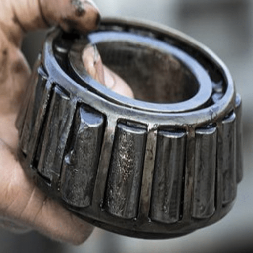
Best Practices for Bearing Steel Cleanliness and Maintenance
To sustain the efficacy and reliability of bearing applications, there should be high cleanliness standards of steel and effective maintenance strategies in place. From my personal experience, I suggest the following actions be taken:
- Steel Cleanliness: To lower stress concentration points, it is of utmost importance to select non-metallic inclusions bearing steels. Non-metallic inclusions bearing steels tend to achieve higher standards. For instance, a maximum oxygen content of 8-10 ppm and sulfur levels below 0.015%.
- Lubrication Practices: The use of lubricants with defined viscosity grades like ISO VG has significant benefits for spalling and surface stress. Controllable contamination guarantees, thorough lubrication, as well as using effective lubricants ends up preventing overheating and excessive wear.
- Environmental Controls: Sealed enclosures and desiccant breathers with filters for lubrication would help lower contamination. Such systems would keep bearings from airborne moisture and particulates that are damaging surfaces and materials.
- Heat Treatment: Induction hardening or carburizing heat treatments achieve precision-controlled surface hardness levels of 58-64 HRC. This aids in the balance between core toughness and surface hardness, lowering the risk of plastic deformation and spalling.
If best practices are followed, I can greatly improve the operational performance and life of the bearings, even under difficult conditions. Also, regular surveillance and targeted active efforts will enhance their trustworthiness.
Optimizing Operating Conditions to Extend Bearing Life
In ensuring optimal operating conditions and bearing longevity, I give priority to several practices. For example, first I give utmost importance to the load that the bearing has to support. I perform dynamic load rating calculations by ISO standards and ensure that working operational loads do not exceed seventy-five to ninety-five percent of the bearing’s C value, or basic dynamic load rating for maximum reliability. Furthermore, I emphasize the importance of operational speed; the limiting speed defined by the bearing manufacturer should always be respected to avoid overheating or failure of the component.
Highly optimized performance cannot be achieved without proper lubrication. The type of lubricant selected depends on the expected operational temperature which, for most industrial applications, is expected to be in the range of -18 to 121 degrees Celsius (0F to 250F). While using grease, I ensure its consistency is application-specific (most commonly NLGI Grade 2) and that it is reapplied according to specified OEM relubrication intervals.
Another equally important aspect is temperature management. Operating the bearings within an environment that is below 180°F (82°C) decreases the chances of lubricant breakdown and material stress. For this purpose, I use efficient cooling methods like external air or oil circulation in high-heat environments. Additionally, keeping alignment and reducing misalignment (ideally 0.05° to 0.15°) can result in lower undesired wear and chances of failure.
With careful checking like vibration monitoring and infrared thermography, I can spot imbalance or undue wear which helps me take timely remedial measures. These actions are based on the requirements of the relevant standard and help the bearings operate with minimal wear for extended periods under extreme working conditions.
Strategies for Reducing Spalling and Pitting in Bearing Surfaces
To address spalling and pitting in bearing surfaces, I focus on preventive and corrective measures intended to reduce surface fatigue and failure. I start by making sure that the bearings are properly sized and selected for the specific load and working conditions. For example, I review dynamic load ratings (C) and static load ratings (Co) in terms of the application’s range of loads and try to comply with ISO 281 bearing life calculation standards.
Lubrication is a significant factor in decreasing the metallurgical contact between surfaces that increases the likelihood of pitting. I select lubricants designed for the specific operating conditions, to contain sufficient film thickness, as denoted by the lambda ratio, which is preferred to be greater than 1 to ensure full-film lubrication under the set conditions.
Surface finishing and hardness also matter. Bearing surfaces are less susceptible to spalling when having a roughness value Ra below 0.2 μm and hardness greater than 58 HRC, as these parameters tend to enhance fatigue resistance under cyclic loading conditions. Further, to enhance bearing survivability in demanding applications, I use precision surface treatments or coatings like nitriding or diamond-like carbon (DLC) coatings.
My active target is steadily focused on ensuring condition monitoring of the bearings through advanced diagnostics like vibration analysis and acoustic emissions for the early signs of surface degradation. The strategies employed have been crucial in extending the operational life of the bearings while minimizing the impact of maintenance work on normal operation.
What is the Connection Between Spalling and Pit Formation?
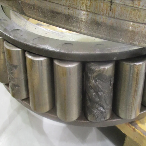
Understanding Spalling from Pitting and Their Relationship
Spalling and pitting are closely related phenomena of surface damage on the surface of bearings. Their progression is different and has underlying causes that serve as distinguishing factors. Pitting initially manifests itself to be small surface cracks forming on the surface. These cracks are a result of very high stress that is concentrated in a specific area due to contact fatigue or material inhomogeneity. As active stress cycles continue to persist, these pits increase in size and ultimately lead to areas of material removal. Spalling, however, is deep pitting. It is far more advanced than the latter with its subsurface conditions being more grave. During deep pitting, greater sections of the material break off.
- Contact Stress: Augmented Hertzian contact stresses that exceed the conditioning limit of the material remarkably increase the chances of frame cracking and subsurface pitting surfaces.
- Material Hardness: The presence of cracks that occur due to fatigue can easily be escaped with surfaces that are harder than 58 HRC.
- Surface Roughness (Ra): Rough edges and surfaces will have a roughness average of less than 0.2 pm aids in lowering the stress concentration and reducing crack formation.
- Lubrication: The use of high-performance oils or greases guarantees effective lubrication which mitigates the contact made by metals which ultimately lowers the surface stress.
- Load and Speed Conditions: Exerting extreme force and speed worsens the cyclic stress which indicates that these operational parameters must be kept in check.
In my opinion, it is necessary to consider these conditions so that both pitting and spalling can be avoided using preventative design modification, surface treatments, and regular condition monitoring to improve the component’s service life.+
Analyzing Surface Contact Fatigue as a Cause
Surface contact fatigue is a consequence of repetitive cyclic loadings at the points of contact between mechanical parts that produce highly localized stress concentrations.
- Material Hardness: Lack of sufficient hardness of the material causes the surface to be strained under load. For materials resisting fatigue cracks, a hardness of 58 HRC or above is ideal as further increased hardness changes their resistance to fatigue-induced cracks.
- Surface Finish: Geometric surface finish leads to increased concentrations of stress, which serves as a precursor to fatigue failures. It is, therefore, necessary for surface roughness (Ra) to be less than equal to 0.2 μm to eliminate risk.
- Contact Stress Levels: At high dynamic loads, excessive strain is inflicted which increases cyclic stress. Contact stress should be managed within the elastic range of material using procedures like Hertzian contact theory.
- Lubrication Quality: Inadequate lubrication increases the likelihood of metal-to-metal contact while increasing stress concentration which reduces the efficiency of an effective oil film formation. High-viscosity grade lubricants with designated performance ratings ought to be used as they greatly mitigate friction and dissipate heat.
- Operational Load and Speed Conditions: Increased load and speed inflict more damage than the material can handle due to fatigue. Keeping operational parameters within the limits prescribed by the manufacturer can greatly increase the lifespan of the equipment.
Taking into account these criteria with the right choice of materials, appropriate surface engineering, and proper maintenance procedures can significantly lessen surface contact fatigue. Additionally, using non-destructive testing (NDT) aids in preventing and managing emerging risks through constant observation. This method improves the life span and dependability of vital parts of the machine.
Frequently Asked Questions (FAQs)
Q: What is spalling damage in bearings?
A: Spalling damage in bearings refers to the flaking or breaking off of material from the surface of the races and rolling elements. It is a common form of damage caused by fatigue and stress over time.
Q: What causes spalling in ball bearings?
A: The primary cause of spalling in ball bearings is the fatigue of bearing material due to repeated stress. This can be exacerbated by improper lubrication, contamination, or misalignment.
Q: How can corrosion contribute to spalling damage?
A: Corrosion can weaken the material of the bearing, creating stress points that accelerate the spalling process. This makes the bearing more susceptible to damage caused by regular operation.
Q: What are the long-term effects of spalling on bearings?
A: Although their causes and long-term effects vary, spalling damage is progressive and can lead to complete bearing failure if not addressed. This increases maintenance costs and downtime.
Q: How does the mechanism of spalling occur?
A: The mechanism of spalling occurs when a thin work-hardened surface layer forms on the rolling element and raceway surfaces. This layer eventually breaks away, leaving wear marks and pits.
Q: What types of surface contact can lead to spalling?
A: Types of surface contact that can lead to spalling include point surface origin contact, where localized stress points form, initiating damage and leading to spalling over time.
Q: How is spalling damage in bearings detected?
A: Spalling damage is typically detected through visual inspection, where wear marks and pitting are evident, or through vibration analysis, which can indicate irregularities in bearing performance.
Q: What solutions exist to prevent spalling in bearings?
A: Solutions to prevent spalling include ensuring proper lubrication, regular maintenance, and alignment checks. Using high-quality bearing materials and addressing secondary damage promptly also helps mitigate risk.
Q: How does spalling differ from other modes of damage?
A: Spalling is the result of surface fatigue and differs from other modes of damage such as corrosion or wear, which may not necessarily involve material removal or flaking.
Q: Why is it important to address spalling promptly?
A: Addressing spalling promptly is crucial because the damage is progressive. Failure to do so can result in more severe secondary damage and potentially catastrophic bearing failure.


