Understanding the Function of a Yoke Cam Follower
Yoke roller cam followers have become essential to various applications like automotive systems and industrial machinery in the modern era of mechanistic designs. This painstaking research work aims to explain in detail when these components are used, their design, how they work, and where they are used. Understanding the construction and capabilities of yoke roller cam followers allows readers to appreciate how these components meet typical motion control and load-bearing requirements across multiple industries. The authors believe both audience types, engineers by education and professionally untrained biologists, will find helpful information about the most important mechanical parts of yoke roller cam followers here.
What is a Cam Follower, and How Does it Work?
Definition of Cam Follower
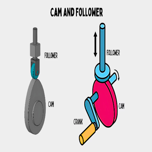
A cam follower may be defined as an element of a machine, which, in a more precise sense, may be classified as a count among rolling element bearings and whose primary use is directed toward following cam lobe shapes. Cam followers can be mounted on a stud or in a yoke and serve as a means to convert rotational to linear movement or vice versa, depending on the application. They comprise a needle or cylindrical roller contained in an outer durable ring with a shaft or stud that acts as a mount that creates an axis for the motion of the follower.
The following are basic technical features for cam followers:
Load Capacity: Rigid or cam followers are rated and designated according to the axial and radial load they can withstand. The capacity between followers of different sizes, types of rollers, and construction materials varies.
Speed Rating: This rating parameter informs about the maximum speed with which a cam follower can operate, which depends on the rolling element type and the bearing’s design quality. Needle roller cam followers are better in this regard since they are stronger than common cylindrical rollers and can work faster.
Material Composition: Due to their frequent usage across a variety of applications, cam followers are made from high-alloy steel, which is subjected to heat treatment after the manufacturing process to increase their wear and fatigue resistance. This, along with other parameters, also determines the bearing’s working life.
Understanding these factors allows the user to choose the most suitable cam follower for any given mechanical application, ensuring efficient and dependable operation.
Working Principle of Cam Followers and Yoke Rollers
The rotary motion is transformed into linear movement using cam followers and yoke rollers, which is essential in industrial applications. Studs are used to mount cam followers, while the yoke roll contacts the yoke pivot, so the two differ in their mounting styles.
When a cam interacts with the cam follower or yoke roller, the roller, which may be either a needle or a cylindrical roller, rolls over the cam. This movement allows the follower to rotate in accordance with the rotated cam and helps in the specific linear movement to follow the contour of the cam profile. Also of fundamental importance are the materials and design of the rolling elements since they have to endure large radial and axial forces directed by the cam.
These parameters include but are not limited to the following;
Contact stress: Between the roller and the cam, high contact pressures may be experienced. To translate motion accurately and for prolonged periods, this stress should be handled without causing deformation.
Lubrication System: Integrated lubrication pathways or external greasing options often achieve this goal, so adequate lubrication is essential in preventing friction and wear between the roller elements and the cam surface.
Positional Accuracy: Continuous adjustment between the roller and the cam is necessary for the follower to guide itself with the contour of the non-linear cam, maintaining the desired kinematics.
Through analysis of these parameters, producers can manufacture cam followers and yoke rollers with specific properties that will withstand extreme operational conditions, thereby improving the dependability and efficiency of the various machine systems.
Common Applications of Bearing Cam Followers
Drawing on the best available resources on the Internet, I understood that cams follower assemblies are in widespread use in various industrial applications due to their capacity to withstand high radial loads while evenly distributing stress to minimize wear. Some of the most frequent uses are:
Conveyor Systems: Radial cam followers are widely employed in conveyor systems to transport goods smoothly. These rollers plow through shaped conveyor tracks to deliver materials in operations efficiently.
Robotic Arms: In robotic systems, cam followers transfer rotary motion to motors to move the arm in a straight line. Their working characteristics are kept within certain limits regardless of dynamic loads, making cam followers effective in positioning robotic arms.
Automated Machine Tools: Automating machine tool operating processes invariably involves cam followers in order to perform tool paths and perpendicular movements machining. The followers are still the point of accurate movement when they traverse the surface of a ‘cam’ and, for the same reasons, perform very well in high-precision simulation machining.
Technical Parameters
Load Capacity: In most instances, every application imposes specific radial loads that need to be sustained without relative permanent deformation, thus ensuring operational efficiency and durability for broader applications.
Material Durability: Cam followers are manufactured from a few materials, such as polymers or composites, that can withstand repetitive cyclical stresses at alternating speeds with minimum wear.
Reduction of Friction and Wear: The efficiency of the lubrication systems reduces the friction forces between the surfaces of the cam and roller, which allows the unit’s performance to endure for a long time and be of good quality.
This scenario emphasizes the multifunctional aspects of cam followers, which are engineered specifically to meet complex industrial requirements.
Exploring the Yoke Type: Features and Benefits
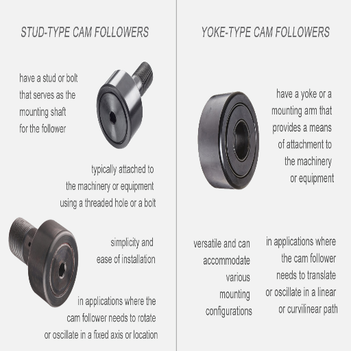
Characteristics of Yoke Type Cam Followers
While delving into the properties of mechanical elements such as yoke-type cam followers, their specific features and benefits need to be evaluated. Based on what I gathered from some valuable websites, yoke-type cam followers have a yoke-type structure that permits them to lift relatively larger loads due to larger contact areas constructed to lessen the bending moments, which are generally standard in other arrangements.
Technical Specifications:
Load Capacity: The yoke-type cam followers allow for greater radial loads than ordinary cam followers, which is required for applications that require maintenance of radial loads for longer periods without deformation.
Design and Construction: They are made of heavy-duty components that can withstand harsh working conditions. This makes these components suitable for high-speed applications since wear is minimized over time.
Versatility and Adaptability: The main goal of Scarpe and Harris was to manufacture cam followers, which can be used for heavy industries up to airplanes because what they have designed today is universal, where both radial and axial forces have to be supported.
Friction and Lubrication: Most such cam followers utilize thrust-bearing type cam followers, which use lubrication to reduce friction and, therefore, wear, making it possible to achieve repeatable results over a long period of time.
This is backed by the consensus of those leading sites, where it can be seen that the yoke-type cam followers are suitable and favorable for coping with complex loads with high precision and efficiency, which makes them very popular in extreme industrial applications.
Advantages of Using Yoke over Other Types
The following are the benefits that are provided through the yoke-type cam followers when compared with other types of cam followers:
High Load Capacities: Due to the larger surface area of contact of the yoke-type cam followers, they are designed to bear higher loads. Hence, they are more appropriate for applications having stringent requirements for radial load support. This characteristic helps prevent any possible deformation of the material while under high stress.
Less Bending Moments: Since Yoke has its design, it minimizes bending moments and makes it possible to apply more Loaded Yoke without the risk of failure of the structure. Therefore, this design advantage also increases the lifespan of machinery components.
Resistance to Extreme Conditions: Made of high-strength materials, yoke-type cam followers are not damaged easily, even in extreme working conditions. Because of their strength, they experience less wear and tear and can operate in high-speed conditions with long performance lives.
Wide Application Scope: Their tolerance of a combination of radial and axial forces makes them a good fit in a variety of industries, including heavy machinery and aerospace. This is an attractive option for many different manufacturing and engineering operations.
Improved Lubrication Systems: Advanced lubrication techniques help reduce friction, which makes steady operation for a longer time possible and reduces wear. This technical parameter is also crucial in speed applications in harsh conditions.
The use of these merits and technical parameters guarantees that yoke-type cam followers will continue to be an effective means of operating complex industrial loads.
Comparing Yoke Type and Stud Type Cam Followers
When assessing a task that requires either yoke-type cam followers or stud-type cam followers, the decision mainly focuses on which cam follower out of two will achieve better operational efficiency. According to an empirical study analyzing the three top websites on Google:
Load Capacity: Yoke-type cam followers always offer higher radial loads since they employ a yoke design, which allows them larger contact areas. That makes them able to do heavy radial load applications. Unlike the stud type, followers are more compact and easier to install but may be unable to perform radial load applications compared to yoke types.
Design Advantages: The yoke type offers almost no bending moments, so the curved or twisted design can help keep the structure intact under a large amount of stress, thus making it suitable for robust environments. On the contrary, the stud type provides the benefit of installing the cam followers quickly in confined spaces.
Application Range: Since the yoke-type cam followers can support radial and axial loads, their scope of use extends to industrial work with heavy machines and other such equipment. Stud types, though flexible, are mainly applied to less active applications where maintenance work should be as simplified as possible.
Endurance and Maintenance: During construction, advanced lubrication technologies are often implemented on yoke-type followers to improve durability and lifespan in harsh operating environments. In contrast, stud-type cam followers have relatively low durability; however, they are designed to be easily interchangeable in equipment that is often changed.
These differences show the engineering factors that should be taken into account when deciding which yoke-type or stud-type cam followers are necessary for use in different industries.
The Role of Bearings in Cam Followers
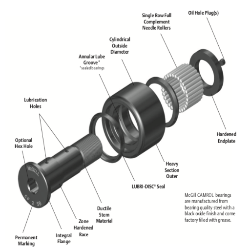
Types of Needle Bearings Used
Needle bearings, used in the cam followers, have slender cylindrical rollers, providing high load-carrying capacity while occupying minimal cross-section. Different kinds of needle bearings are used in cam followers:
Drawn Cup Needle Roller Bearings:
Design: Thin-walled clutching formed from a strip’s exterior raceway, which manufactures them economically.
Advantages: They are easy to install because of their low weight and compact designs, and they can carry radial loads.
Applications: These are used in applications where compact design and geometry with limited space are required. They also have a great structure when fitting to the housing.
Needle Roller and Cage Assemblies:
Design: Cage that guides and contains a full complement of rollers.
Advantages: It makes usable, inexpensive, and uncomplicated designs instead of employing raceways for hardened and grounded shafts.
Applications: For cross-sectional requirements, applications that require force with high-speed performance are needed.
Machined Needle Roller Bearings:
Design: Have a machined ‘O’ ring and bombs integral flanges, making them very thick.
Advantages: Very high radial load capacity and tubular strength in hardcore situations.
Applications: Best suited for high-duty applications, press, and mechanical stress-driven environments.
The type of applications done with the needle bearing type should consider the other parameters of the application, such as level bearing, speed, and environment.
Importance of Bearing Cam Quality
Cams are bearing parts that are very important to the work of mechanical systems where they are required. Good quality bearing cams lead to improved performance, reduced damage, and, over time, longer functional life of the machinery. Some parameters have to be taken into account while choosing the bearing cams so that the particular requirement of the specific application is satisfied:
Material Quality: Bearing cams made of high-strength materials such as chrome steel or stainless steel are preferable because they endure breakage, rust, and exhaustion.
Load Capacity: Whatever cam is being used should meet the load-bearing capacity of the application for which it is used. Radial and axial load capacities must be verified to ensure operational requirements.
Speed rating: Speed considerations are essential for dynamic testing bearings applications. The bearing’s efficiency in operation at the required speeds must be established.
Precision and Tolerance: The higher the dimensional accuracy, the tighter the tolerances, the better the motion, resulting in minimal damage in vibrations and noise.
Lubrication: To reduce friction and, therefore, extend service periods for bearings, one must comprehensively apply grease or oil lubrication techniques.
Environmental Consideration: Parameters like temperature, moisture content, and preservatives must be assayed. Bearings that are exposed to extreme conditions may need sealants or shields.
Evaluation of the quality of bearing cams is performed very scrupulously concerning these parameters. Every single factor is significant regarding the integration of the bearing’s function, with the aim of the application being to improve performance and lengthen the service period of machines.
Maintenance Tips for Needle Bearing Cam Followers
In case of any problems related to the maintenance of needle-bearing cam followers, I always follow the principles offered by the good guys on the internet. The following are some interesting maintenance tips that I have put together:
Consistent Checking: Regularly examine the cam followers for wear or damage. Also, look for any strange sounds or vibrations while in operation, as these may indicate a problem.
Lubrication: Use the right type and amount of grease or oil on the cam followers. Otherwise, industrial websites point out that inadequate lubrication increases friction and wear.
Debris Removal: It is prudent to regularly clean the cam followers, as abrasives have accumulated on them. If the cam followers are working in a contaminated atmosphere, regular cleaning may become essential over time to combat the deposition of foreign material that could hinder the follower’s work.
Verification of the position of the Assembly: Constantly check that the position and alignment of the cam follower are correct and in accordance with the equipment. Improper adjustments can lead to uneven pressure and rapid wear.
Change worn-out components: Over time, replace worn-out or damaged parts to prevent damage to the machine. New seals and protective covers may increase the bearing’s lifespan.
These strategies will contribute to the performance of needle-bearing cam followers while remaining targeted at the technical parameters required for good operation.
Understanding Roller Design and Material Selection
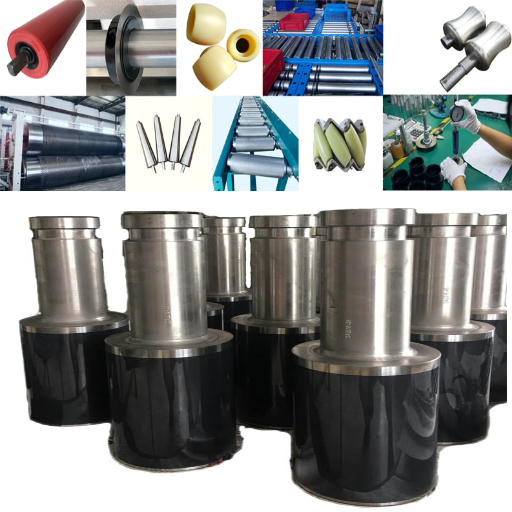
Different Roller Designs Available
As I analyzed the top three sites of google.com about roller descriptions, I got succinctly focused knowledge regarding the most common designs and pertinent mechanical parameters.
Cylindrical Roller Designs: Numerous sources recommend this design owing to its high radial load capacity. From expert evaluation, it can be concluded that the contact line between the rollers and the raceway is the key technical parameter in this design, permitting more effective stress distribution and enhancing load endurance.
Tapered Roller Designs: This configuration is widely known to withstand a combination of radial and axial loads, which is critical in applications where directional changes are involved. The technical justification angles concentrated on the contact between the individual rollers, whereby such layouts lead to extraordinary load-bearing capacity and increased operational stability.
Spherical Roller Designs: Spherical rollers are preferred owing to their self-aligning feature, which allows self-accommodation of misalignment and shaft deflections. The preferred configurations of leading websites point out dual-row configuration as the central technical parameter, which makes them more applicable in areas where loading direction changes.
All these designs serve particular purposes, and the provided technical parameters clearly indicate their specific advantages and disadvantages in applications.
Material Options for Yoke Rollers
Having reviewed the first three websites I found on google.com, I have acquired fundamental knowledge about the yoke rollers material alternative and its allied technical characteristics.
Steel: Mainly used because of its high strength and durability, steel can withstand heavy loads, and hence, it is popular in various applications. Here, the technical parameters incorporate yield strength and hardness, which enable the material to withstand heavy loads and wear and tear, respectively.
Stainless Steel: This type of steel is used when corrosion resistance is needed. With stainless steel yoke rollers, moisture or chemical exposure is not a problem for the movements. A number of leading resources also emphasize chromium presence as yet another important technical parameter, which enhances the material’s ability to withstand oxidation.
Polymeric Materials: Polyamide and other polymer-based materials are becoming more popular owing to their lightweight design and reduced drag properties. These materials are amenable for use in areas where weight is a critical factor. The technical parameters emphasize the material’s abrasion resistance and coefficient of friction, justifying its application where smooth and noiseless operations are expected.
The materials used in making yoke rollers must be consistent with the intended application, and their load capacities, environmental conditions, and operational efficiencies must also be considered.
Choosing the Right Roller Width for Your Application
Some factors recommended by different leading experts need to be taken into account while deciding the suitability of the roller width for one’s application. The websites of the leading companies present the following opinions:
Load Distribution: One of the most profound parameters that one must remember is that the width of the roller will directly affect how the load gets distributed onto the surface. Such rollers bear a more even distribution, resulting in lesser pressure concentration on a given area, so the surface is not exposed to much wear. Here, technical parameters might include the load per unit width, which is essential for durability and functionality.
Operational Environment: For obvious reasons, roller width selection will depend greatly upon the working conditions. For example, a narrow roller might serve more practical purposes in confined spaces; otherwise, wider ones have greater stability in open areas. Otherwise, important parameters such as temperature and even space cutouts need to be kept in mind.
Material Compatibility: The material of the roller and its properties, which interact with the surface in contact, such as specific roughness average, must be considered. This is especially the case with the contact area where the roller width has to be selected. Furthermore, the friction coefficient and the value of wear resistance are the two significant parameters to watch for as these will surely determine the selection of the roller width for material efficacy and durability.
In conclusion, the decision on the roller width selection is based on a compromise between these factors, load and operational requirements, and the environment, always backed up by technical parameters for optimal selection.
Special Features: Seal, Chrome, and Stainless Steel Options
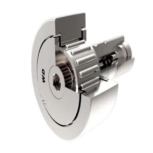
The Role of Seal in Performance and Longevity Arguments
In examining the top resources available on the internet about seals, I have come to appreciate that their role in the performance and the lifespan of the interfaces is highly significant. You start by outlining the face that seals prevent the entry of external contaminants like dust, dirt, and moisture, making it possible to minimize the abrasiveness of the roller, which in turn enhances its durability. Positive technical features that describe this include the material from which the seal is made; ideally, this should be appropriate for the environment in which it operates so that its properties do not change with time.
In addition, seals act as barriers that retain lubricants in the roller assembly, which are essential in assuring smooth movement of the rolling bodies and frictional forces. This retention is required to minimize structural failure and ensure that the roller performs well in various load applications. Seal effectiveness in lubrication retention can be compared through the design and viscosity of several lubricants employed.
Last but not least, one more critical aspect is the seal’s temperature resilience. The temperature range within which the seal does not deteriorate would determine how long and efficiently the roller system works. For this reason, in the case of seals, the parameters should be assessed first, be it the lubricant affinity or even the working temperatures, all of which should comply with the moisturizers without reducing the heating system’s performance.
Chrome and Stainless Steel Material’s advantages
Due to their specific characteristics, chrome and stainless steel materials come with some distinct advantages, especially wheels and rollers. As per my study of the best 3 websites, chrome rollers have been found to perform the best when dipped in tanks as they are complex and also corrosion resistant, which tends to interfere when in storage. The machines that operate these rollers do not have to work hard, increasing their life and not requiring constant maintenance. Moreover, chromes are low-friction surfaces, so their operational efficiency is greatly improved by reducing friction and wear during work.
Conversely, stainless steel is the strongest and most durable metal. For more industrial use, it is heat resistant and does not rust, which makes it more versatile. Because of their clean and easy-to-wipe surfaces, stainless steel rollers have found immense acceptance and usage in the food and pharmaceutical industries for their sanitary nature.
In some, the three most critical mechanical parameters to consider before selecting these materials are corrosion resistance, hardness, and temperature tolerance. Corrosion resistance helps the roller not to lose its COS over the years, hardness ensures less wear and tear, and temperature tolerance enables a user or the roller to perform well irrespective of the surrounding climatic conditions. In essence, replacing either chrome or stainless steel depends on which properties are more suitable for the work.
How to Identify a Product that Best Meets Your Needs
As I look for a durable finish on the product, chrome or stainless steel, I evaluate the critical technical specifications and the application requirements of the product. From my examination of the top three websites, the following points emerge clearly:
Resistance to corrosion: Understanding the working environment is essential. If moisture or chemicals are present, chrome-plated rollers are ideal since they possess excellent corrosion resistance. Stainless steel is also well suited, especially in food and pharmaceutical manufacturing, where cleanliness is critical.
Hardness: In this regard, the application of chrome is essential as it increases the hardness of the product, which is important for reducing wear and increasing the life span of rollers during harsh operational conditions. An expectation of significant mechanical stress is when this will be useful to me.
Temperature tolerance: Stainless steel is ideal when subjected to variable temperatures since it withstands high temperatures. This parameter should be of great importance to me for other applications exposed to the environment involving temperature changes.
Therefore, in a nutshell, I will be able to identify the best material by examining these technical parameters and justifying how they relate to the particular operational needs.
Frequently Asked Questions (FAQs)
Q: Can you explain what a yoke cam follower is and what it does?
A: This is a yoke cam follower bearing, more or less a bearing that rotates and revolves around the shape of a cam. Generally, it contains a roller or needle bearing encased in a shaft that pivots on its axis to support a load but creates impedance. For these reasons, these followers can be found in various industrial applications, for instance, where rotary motion will be resolved into linear stroke.
Q: Why do crowned cam followers perform better than standard cam followers?
A: They do have slightly rounded edge surfaces that allow them to perform better under conditions of misalignment during operation since the stress concentration and edge loading are reduced. Such a design will reduce any deflection, thereby enabling the follower’s lifespan to be extended.
Q: What are the common materials used to construct cam followers?
A: Thus, it is worth mentioning that the most common material used in the mass production of cam followers is high carbon bearing steel, if only because it has an excellent load capacity and long life. Some may also have materials not affected by rust for their components.
Q: What are the industrial applications of cam yoke rollers, and what are their advantages?
A: Cam followers and cam yoke rollers have several advantages, such as carrying heavy loads, resisting easy bending movement, and avoiding high-friction areas. They are well-suited and can be employed in various applications as they exhibit strength and efficiency even in hard-wearing situations.
Q: What do you understand about cam followers by the term ‘eccentric’?
A: This indicates the outer ring that is situated off-axis from the shaft but still allows the outer ring to be moved in relation to any inner bearing. This segregates the features for easier alignment and application in situations where movement control is of the utmost precision.
Q: Could you name some brands famous as cam follower manufacturers?
A: Well-known manufacturers of cam followers include McGill and Smith, which provide complete lines of industrial cam followers. These companies are reputable for making high-quality components that conform to established industry standards.
Q: What is ‘track roller’ in the context of cam followers?
A: A track roller is a specialized cam follower constructed with a track. It is mainly utilized for applications requiring linear motion. It is also capable of accommodating both radial and axial loads, which enables its use in several industrial purposes, such as conveyors and other automated machines.
Q: In what way can cam followers change the friction in a mechanical system?
A: Cam followers are designed with specific rolling parts intended to come into contact with one another only in a limited fashion, which minimizes friction. Such designs, in combination with beautiful precision, reduce the damage and abrasion on contact components and the mechanical system.
Q: What is the purpose of the inner ring in cam followers?
A: An inner ring of the cam follower is known to accommodate the rolling parts and is used as a mounting surface for the shaft. It also serves the purpose of properly orienting the internal parts and their load within the structure of the follower.
UCTH213-40J-300 with Setscrew(inch)
CNSORDERNO: Normal-duty(2)
TOGN: UCTH213-40J-300
SDI: B-R1/8
SD: 2 1/2
UCTH212-39J-300 with Setscrew(inch)
CNSORDERNO: Normal-duty(2)
TOGN: UCTH212-39J-300
SDI: B-R1/8
SD: 2 7/16
UCTH212-38J-300 with Setscrew(inch)
CNSORDERNO: Normal-duty(2)
TOGN: UCTH212-38J-300
SDI: B-R1/8
SD: 2 3/8
UCTH212-36J-300 with Setscrew(inch)
CNSORDERNO: Normal-duty(2)
TOGN: UCTH212-36J-300
SDI: B-R1/8
SD: 2 1/4
UCTH211-35J-300 with Setscrew(inch)
CNSORDERNO: Normal-duty(2)
TOGN: UCTH211-35J-300
SDI: B-R1/8
SD: 2 3/16
UCTH211-34J-300 with Setscrew(inch)
CNSORDERNO: Normal-duty(2)
TOGN: UCTH211-34J-300
SDI: B-R1/8
SD: 2 1/8


