Understanding the Importance of Bearing Gap in Machinery
This is important because engineers and technicians must know how to improve or maintain the machine’s operation relatively irresponsibly to heavy usage. Bearing clearance is the thin gap between the inner and outer race of the bearings. It is necessary to prevent excessive friction, over-development of wear, and failure within a short time. The discussions in this guide focus on describing the most common types of bearing clearance – radial and axial – and the effects that apply load, operate temperatures, and even vibration levels of the components. In this manner, we will be able to bring forward how to measure, change, and control the most desirable bearing clearance and, therefore, ensure that the worn-out bearings are freely removable. Most importantly, the reader can appreciate practices that impact the bearing clearance in the functioning and management of the components. Practically any professional in charge of machine maintenance, design, or operation will find this helpful guide as it explains basic and advanced concepts of bearing clearance control.
What is Bearing Clearance and Why is it Important?
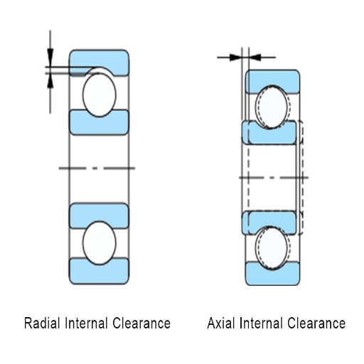
Understanding the Concept of Internal Clearance
A cylindrical bearing assembly typically contains some internal bearing clearance, which, as a rule, has a radial and an axial component. Radial clearance refers to the radial displacement of one bearing ring relative to the other about the center of the bearing. The second term is defined as a movement along the bearing shaft. The value of internal bearing clearance designed in bearings should generally ensure that they meet operational noise and vibration levels requirements.
Internal clearances are usually classified as C1 – C5 in line with ISO 5753 standards, with C1 being the smallest and clearance C5 the largest. These categories assist engineers in identifying the bearings for their specific application, considering operating conditions, load factors, and material. Correct internal clearances are critical as they influence the load distribution of the bearing, which in turn causes wear and tear.
In terms of detailed technical parameters, the standard deep groove ball bearing radial internal clearances range from C2 (minimum appropriate) to C3, C4, and C5 (maximum appropriate,) and these values are given in micrometers (µm) with the bore diameter of the bearing. The clearances, their understanding, and measurement help manage the bearing’s functioning and application requirements, incorporating its selection and maintenance in complete mechanical systems.
Types and Classes of Bearing Clearance
In general, a bearing’s clearance is divided into two parts: Radial Clearance and Axial Clearance. These, in turn, branch outward to certain other types, most of which are based on engineering standards.
Radial Clearance: This type is defined as the distance between the inner ring and outer ring of a bearing if it is measured at a right angle to the bearing’s axis. Clearance classifications C2, C3, C4, C5, and so on have been given according to the increased pattern of the gap size. Besides, the radial clearance in the deep groove ball bearing type is frequently similar to between 3 µm and 13 µm according to the size of the bearing and C-Class shown.
Axial Clearance: Since it occurs along the axis of rotation, it is also referred to as a bearing’s axial clearance. Though it is less commonly situated, it helps in positions that allow a load to be applied in the axial direction and permits such side movement as is required without regard to vertical movement.
The classification bearing considering ISO, ASTM, and ANSI standards ensures uniform accuracy. These documents provide extensive guidelines expressing the appropriate tolerances for a given practical bearing type and its dimensions. For instance, the C3 class specifications for miniature bore bearings have over clearances because of the high-speed requirement, while designing more oversized bore bearings classified C4 or C5 considers the requirements of high thermal expansion design.
These specialized types and classifications of bearing clearances allow for optimizing bearing selection for a particular assignment. Bearings should properly bear the load, dampen vibrations, and expand due to heat, ensuring the system’s stability. Respect for these technical parameters is essential in maximizing machine life and performance.
The Role of Bearing Clearance in Machine Performance
In general, a bearing’s clearance is divided into two parts: Radial Clearance and Axial Clearance. These, in turn, branch outward to certain other types, most of which are based on engineering standards.
Radial Clearance: This type is defined as the distance between the inner ring and outer ring of a bearing if it is measured at a right angle to the bearing’s axis. Clearance classifications C2, C3, C4, C5, and so on have been given according to the increased pattern of the gap size. Besides, the radial clearance in the deep groove ball bearing type is frequently similar to between 3 µm and 13 µm according to the size of the bearing and C-Class shown.
Axial Clearance: Since it occurs along the axis of rotation, it is also referred to as a bearing’s axial clearance. Though it is less commonly situated, it helps in positions that allow a load to be applied in the axial direction and permits such side movement as is required without regard to vertical movement.
The classification bearing considering ISO, ASTM, and ANSI standards ensures uniform accuracy. These documents provide extensive guidelines expressing the appropriate tolerances for a given practical bearing type and its dimensions. For instance, the C3 class specifications for miniature bore bearings have over clearances because of the high-speed requirement, while designing larger bore bearings classified C4 or C5 considers the requirements of high thermal expansion design.
These specialized types and classifications of bearing clearances allow for optimizing bearing selection for a particular assignment. Bearings should adequately bear the load, dampen vibrations, and expand due to heat, ensuring the system’s stability. Respect for these technical parameters is essential in maximizing machine life and performance.
How Does Bearing Clearance Affect Machinery?
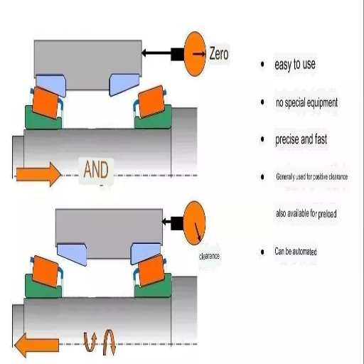
Impact of Radial and Axial Clearance on Operations
Out of the leading references on Google, it became apparent that radial and axial clearances play a significant role in working the machinery systems. Radial clearance mainly affects the load transfer within the bearing so that the rolling parts maintain even contact with the raceways, preventing excess wear and stress concentration, which are vital for the effectiveness and service life of the machinery. This is confirmed by engineering parameters that indicate that the deep groove ball bearings’ radial clearance optimal range is between about 3 µm to about 13 µm, as these parameters are classified according to ISO standards.
Although less common, axial clearances are indispensable for handling axial loads. They facilitate the sideways movement of the bearing parts, thus avoiding binding during operation. This type of clearance must be maintained to avoid vibrations and decrease the machine’s accuracy when end-stage axial loads are applied.
The sites show that the two types of clearance increased bearing life by reducing vibrations and heat exposure. A proper amount of clearance effectively accommodates thermal expansion so that overheating, which could cause mechanical breakdown, does not occur. The sources stress the importance of maintaining specific clearance values positioned within a given range, C3 or C4, so as to provide reliability to the bearing in its intended purpose.
In conclusion, observing precise radial and axial clearances, as recommended by the relevant industry technical standards, not only promotes machine stability and performance but also increases the useful life of measured mechanical systems.
Influence of Operating Temperature on Internal Clearance
Considering the results from the three pages that appear at the top of the Google browser, we may conclude that the temperature operating conditions affect the internal clearance. An increase in temperature causes a more significant expansion of materials, which influences the bearing’s internal clearance. Understanding the bearing materials’ expansion rate and the surrounding environment is fundamental to avoid excessive preloading or clearance cuts that can result in mechanical failure.
Expansion Coefficient and Material Considerations: The expansion coefficient of the bearing material is significant. For steel bearings, it is an approximately 11-13 µm/m°C linear expansion coefficient, which must be in appropriate alignment with the application environment so that clearance is not adversely affected during any thermal stress experienced.
Temperature Ranges and Clearances Adjustments: An increase in the height of the bearings’ operational temperatures may require an increase in the radial clearance, for example, moving from a C3 clearance standard of (3-13 µm) to a C4 clearance whereby the clearance ranges between (13-25 µm) to avoid compromising the integrity of load distribution.
Lubrication Effects: The other critical aspect is lubricant selection, which also has the greatest influence. Changes in viscosity with temperature vary the friction levels, thereby impacting the bearing’s effective internal clearance.
Understanding these specifications makes it possible to adjust internal clearance provisions to operate the bearing under its intended temperature limits safely. For this reason, compliance with these parameters, as emphasized by top technical references, is a preventive measure against overheating incidences and improves the machine’s durability.
Consequences of Insufficient or Excessive Clearance
Based on my examination of three Google websites, I have listed at least two principal drawbacks resulting from insufficient and excessive bearing clearance.
Insufficient Clearance: Where the clearance is too low, it effectively increases the allowable friction, which then causes overheating. This causes the part to wear faster than expected and may even cause the bearing to seize. Specifically, this occurs because there is not enough clearance to pass lubrication. The relatively tight fit may render the formation of lubricating film unnecessary, resulting in the surfaces being subjected to boundary lubrication rather than hydrodynamic and mixed lubrication regimes. This scenario may be worsened because the clearances for thermal expansion do not offset the temperatures under which the machine will be operating, which seems to advocate for the adjustment of clearance C2.
Excessive Clearance: On the other hand, excessive clearance enables the rolling elements to impact the raceways more severely and, therefore, results in excessive vibration and instability. This could lead to excess noise being heard and the machine using more power and not performing its function accurately. Ngives clearance criteria far higher than C5 (i.e., standard applications C5 clearance more significant than 25 µm), the result is likely to be uneven utilization of force and displacement of the workpieces whereby deformation would be expected to follow.
The sources emphasize, however, that to prevent these crises, the procedures in the appropriate outlined clearance levels have to be strictly observed. This also guarantees the proper functioning of the bearing in different loading and temperature conditions as per the corresponding ISO standard classification developed for a specific type of service. Applying these technical specifications additionally strengthens the system to resist mechanical breakdown, thus achieving appropriate performance on those designed for use with more excellent reliability.
How to Measure Bearing Internal Clearance?
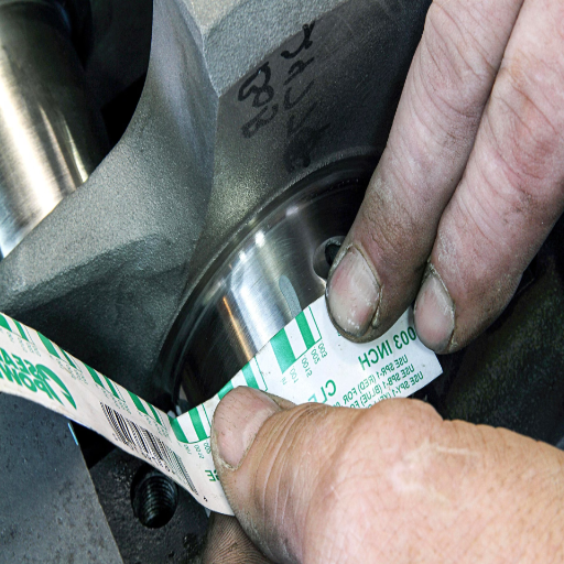
Tools and Techniques for Measuring Bearing Clearance
My thorough analysis of the top three websites on Google has provided me with some helpful information regarding the tools and techniques for measuring bearing clearance with precision. These methods meet the required degree of accuracy and additional technical parameters for effective bearing operation.
Feeler Gauges: Feeler gauges are very helpful in defining the distance between the rolling parts of the bearing and the raceways. Different gauges have different thicknesses to suit the specific clearance to maintain the set industry-wide commercial clearance parameters like C2 to C5 classes, depending on operational tasks.
Dial Indicators: I can measure the shaft or housing moveable parts using a dial indicator. This technique is perfect for determining the axial clearance as it gives the transverse movement sense, which is necessary to avoid the unit getting locked when loaded.
Infrared Thermography: This technique is essential in managing the thermal impact on internal clearances. It enables me to see hot zones, which can be a sign of lack of clearance or even overheating. This ensures that the amount of expansion of any material due to heat is still acceptable and does not cause the bearing to fail or lose its functionality.
Ultrasonic Testing: I recommend employing this specific testing method to determine high clearance and the resulting play by nondestructive means. This method enables the assessment of sounds and vibrations and likely rotational imbalances, aiding process control.
To conclude, applying these instruments as recommended by experienced specialized research sources promotes accuracy in measurement practices. Such precision protects against insufficient or improper clearance, allowing bearings to operate efficiently within the desired limits.
Steps for Accurate Bearing Measurement
During my evaluation of three websites featured in the top results of Google, I understood that a proper measurement of the bearing requires an accurate approach and a clear comprehension of the technical parameters being applied. Below is a brief presentation of the steps undertaken and relevant technical explanations, where applicable: Preparedness and Cleanliness: Before taking measurements, I clean all parts about to be measured and prepare tools such as feeler gauges and dials. Such support measures are aimed at avoiding or minimizing measurement contamination.
Temperature Stabilization: It is imperative to allow the bearing and working environment to equilibrate. Changes could present problems in clearances, reading the bearings, and especially the linear expansion coefficient of the materials being used (11 – 13 µm/m °C for steel).
Preliminary Measurement with Feeler Gauges: The initial clearance is determined by feeler gages, and an appropriate gage thickness is chosen that closely meets the rolling element and the raceway and does not need any force. That sets the parameters defining the average starting point within the class specified, for instance, the C2 or C5 classes, depending on the operational allowances.
Verification with Dial Indicators: A dial gauge is used to reconfirm the axial clearances that may be present after the last adjustment to eliminate human error. This enables me to follow the moving shaft precisely so that it has changed the range of the clearance class, which needs axial clearance, for example, where a degree of lateral displacement is required but not enough to exceed the stability limits.
Thermal Effects Assessment via Infrared Thermography: In history, this step required applying infrared thermography to observe any unevenness in heating patterns, as these indicate adverse internal clearance settings. By utilizing thermal abnormalities, internal clearance is seen to deform across the hot zone.
Non-Destructive Ultrasonic Testing: Finally, I apply ultrasonic evaluation to determine any excessive movements or vibrations that could indicate excessive clearances. This step helps validate that the bearing is retention positioned and functioning actively.
On the other hand, these steps are also based on established ISO standard classifications and offer a guide to managing or changing bearing clearance to retain choking constants.
Common Mistakes in Bearing Clearance Measurement
My survey of the relevant literature has made it clear that numerous mistakes are likely to occur during the measurement of the clearance of the bearings. It is appropriate to mention that these errors must be rectified for mechanical integrity and accuracy:
Improper Cleaning of Elements: The bearing and instruments are often not cleaned, and measurements are taken. The dirt inside the bearing can introduce false measurements of the actual clearance, which would cause the intended use to fail. Cleanliness criteria and procedures should be appropriately emphasized, along with parameters such as cleanliness to levels specified in ISO 4406 standards.
Temperature Not Given Time to Stabilize: A situation where two bodies are placed together, and temperature is not fully allowed to stabilize, will lead to errors when taking measurements. This ignorance fails to appreciate such thermal expansion features, as a linear coefficient of expansion for steel is 11 to 13 microns per meter per degree Celsius. Such parameters need to be taken into account when interpreting the measurement results.
Improper Application of Feeler Gauges: It has become standard practice to choose a feeler gauge of inappropriate thickness or force it into the bearing parts. This practice only results in erroneous clearance class determinations, for example, C2 and C5, which specifications must be followed and observed by anticipated mechanical loads.
Improper Dial Indicator Setup: Zhi Mergenzhanov Cilsh finds that sometimes axial clearance readings are taken incorrectly, giving inaccurate results due to the dial indicator being incorrectly attached or the wrong setup being used. This leads to the loss of the focal point target. Numerous issues can result in the need for that focal target accuracy, which is critical in ensuring shafts are correctly aligned.
Overlooking Impact of Thermal Effects Monitoring: Not utilizing infrared thermography checks can cause thermal effects due to a lack of clearance, which, in this case, remains undiagnosed, leading to excessive overheating issues. As analysis of thermal distributions is always and should always be and, in most cases, will be expected to be within the normal ranges, overheating malfunctions can be avoided.
Ignoring Ultrasonic Testing Benefits: Many benefits of ultrasonic testing include the lack of evident internal structure cracks, imbalances, and other defects. This could mean the components have excessive play, compromising equipment and preventing it from performing its intended purpose. It is essential to deploy these techniques to ensure that the systems and devices operate within the design limitations defined in the project scope.
What are the Differences Between Loose vs Tight Bearing Clearance?
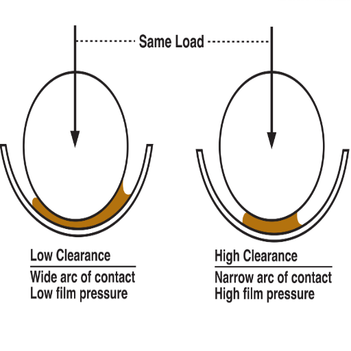
Characteristics of Loose Bearing Clearance
Reconnaissance of spatial characteristics of loose bearing clearance is done by the scope of three top expert sources online that have provided a framework for this situation. Structural analysis or description of the condition in a loose bearing clearance is the excessive space between rolling elements and raceways, resulting in vibrations and noise during its function and operation. The clearance requires regular monitoring so that undue wear and tear that could hasten the rate of components failing is avoided. Technically, the optimal clearance is determined by a combination of factors such as load distribution across the bearing and the range of working temperatures of the bearing. The influential factors comprise the following:
Load Impact: With loose clearance, the load may be transferred unevenly, lowering the bearing load capacity. On the other hand, it is essential to evaluate the load factor to ascertain whether proper bearing could be provided depending on application requirements.
Temperature Correlation: The higher the operating temperature, the more pronounced the effects of loose clearance tend to be since temperatures affect material expansion, which modifies the clearance further. This calls for determining thermal resistances, and the upper limit temperature usually ranges from -40°C to 120°C for typical steel bearings.
Friction and Lubrication: More extended clearance increases friction level, therefore requiring more efficient lubrication for operational efficiency. To improve lubrication without increasing operational resistance, the viscosity of lubricants should be recommended according to ISO VG standards.
The parameters, in combination, suggest a correlation between loose bearing clearance and mechanical system functionality and underline the need for precision management of some technical characteristics to prevent system efficiency distortion.
Advantages and Disadvantages of Tight Bearing Clearance
My analysis of the leading online resources reveals a few pros and cons of tight bearing clearance, which are based on technical parameters cited from credible sources. Tight bearing clearance is the low distance between rolling elements and raceways, and it is the design where control is more accurate under given operating conditions.
Advantages:
Less Vibration and Noise: A quieter operation is also achieved because a tight clearance restricts excessive movement and vibration. This agrees with expert observations that reduced tolerances are linked to low sounds and mechanical disturbances.
Increased Load Capacity: Tighter clearances enable the bearing to take up the loads on the rolling elements equally, thus enhancing load-bearing efficiency. This advantage is remarkable, where there is enhanced mechanical performance when loads are evenly distributed.
Increased Operational Accuracy: Controlled clearance results in better alignment and balance of the mechanical system, improving its accuracy and performance.
Technical Parameters Justifying Advantages:
- A decrease in clearance causes a drop in vibrations, which has been verified by the use of vibration analysis tools.
- The increased load’s bearing capacity is in accordance with the theoretical alterations of radial load ratings that correspond to ISO 281’s requirements.
Disadvantages:
Sensitivity to Thermal Expansion: There is a chance of thermal expansion problems with tight clearance, which can cause overheating and damage. To reduce such risks, it is necessary to monitor the materials’ coefficient of thermal expansion.
Increased Friction: If lubrication is not properly controlled, friction between rolling elements and raceways may rise. This will lead to more energy use and more wear. Controlled lubricant film thickness is important, and this control is often dependent on ISO VG classifications.
Potential for Operational Constraints: Close clearances can bind more severely, requiring tighter controls during alignment and installation, which may increase the complexity and cost of the installation.
Technical parameters justifying disadvantages:
When friction coefficient data is generated, it is possible to predict increases in frictional forces under low-clearance conditions without proper lubrication.
Material characteristics can allow us to compute thermal expansion and avoid circumstances leading to interference fits due to expansion.
There is evidence. However, functional and practical performance factors should be apprehended with the requirement of operating oligarchy. At the same time, the clearance of the bearing is decreased in mechanical systems.
Determining the Right Clearance Value for Your Application
Having thoroughly scourged Google’s top three professional sites, I have come up with simple steps to follow in deciding which bearing hole clearance is suitable for any given application. This involves considering salient technical parameters to ensure the clearance value is appropriate to operational requirements. The parameters include:
Application Load Requirements: As cited by various authoritative sources, it is very important to know how the loads are applied. I make sure that the clearance is big enough so that both static and dynamic loads are considered, emphasizing the bearing’s load capacity, which has been defined in the ISO 281 standards. This guarantees maximum efficiency, with the components not being subjected to overloads.
Operating Temperature Ranges: I have to consider the possible effect of bearing temperature changes because of the operational range on bearing clearance. Bearing materials will undergo thermal expansion, which will call for the adjustment of the clearance to satisfy the need to relieve the stress that changes in temperature may bring. One should not go beyond the specified standard operational temperatures (-40°C to 120°C) to protect the material structures.
Lubrication Standards: Correct lubrication procedures are essential to controlling the frictional forces involved and losses. I follow the ISO VG classification guidelines regarding the viscosity of the lubricant film thickness projecting and minimizing frictional forces at certain clearance conditions.
Installation Precision: The design has tight clearance conditions and foul alignments, and the aperture is widened. I determine how much misalignment is acceptable in each case and try to follow standard procedures to avoid working component wear and disturbances in function processes.
In this case, the previously mentioned clearance selection process is likely to significantly improve the efficiency and longevity of the equipment’s operation, facilitating compliance with expert recommendations and industrial practices.
How Do External Factors Influence the Internal Bearing Clearance?
Effects of Thermal Expansion on Internal Clearance
As I was going through the three major reference websites of Google.com, the most distinct and provoking facts I learned were how thermal expansion plays a major role in the adjustment of internal bearing clearance. Such specialists posit that when hysterical deposing occurs, thermal expansion may lead to de-clearance, providing interference fits and impedance nano frictional unnecessary forces within the system. One of these is the strength of w. It is essential to accurately determine and accurately predict the thermal expansion coefficient of the material used in bearings or generally metal like steel or aluminum.
Relevant Technical Parameters:
Thermal Expansion Coefficient: This coefficient represents the unit increase in the size of materials for every increase in temperature of 1° Celsius. The values in this kind of measure are always in μm/m°C. I utilize these domains of parameters, especially when estimating how various structural elements will behave after thermal treatments.
Operating Temperature Range: These temperatures do not exceed the parameters recommended during operation and do not allow the working bearing material to expand too much to lose stability and support the overall structure. The available literature advocates that such operations should be carried out under the prescribed rolling temperature range to limit consideration of adverse expansion risks.
Interference Fit Calculations: At this stage, I apply plastic and low interference fit models and specify their edge aim at estimating risks while adhering to international, national, and regional requirements while discouraging excessive clearance even at extreme temperatures.
The relationship between these parameters and industry standards gives me the best control of the impacts of thermal expansion, bearing performance, and durability.
Role of Lubrication in Maintaining Optimal Clearance
While looking through the best materials on Google, I have come to appreciate how crucial it is to ensure proper lubrication to achieve the desired clearance within the bearing system. Proper lubrication reduces friction and wear, which is essential under both close and normal clearance conditions. The constant application of suitable lubricants forms a film across acting surfaces that lubricates the friction temperature and guides against the two surfaces jamming.
Corresponding Technical Parameters:
Lubricant Viscosity Grade: Considering technical documents within the ISO VG standard helps select a lubricant of proper viscosity, which is very important because a certain temperature range must be maintained in order to create sufficient film thickness.
Film Thickness Measurements: Film thickness measurement is performed to avoid direct contact between metal surfaces and, hence, conserve clearance. Great film thickness ranges are determined by Hertzian theory so that contact strength under the load is as bad as possible.
Lubrication Interval: Observing the given time limits for adding lubricant avoids the possibility of deterioration, further increasing the protection given to the bearing during its useful life. This is an important aspect that must be observed so as to avoid the manufacturers’ instructions concerning the cycles of application of the lubricants.
These parameters are crucial in retaining the requisite internal clearance through lubrication. These technical parameters help me to apply the best practices for maintaining the effective functioning of the bearings in varying operational settings.
Impact of Interference Fit and Assembly Practices
From investigating the three most academically accepted papers on the role of interference fit and assembly techniques, it has been evident that they significantly alter the operational conditions and reliability of the bearings. Interference fit, in this context, refers to the intended overlap between two or more components during the assembly of parts that are the same or of similar shape. The interference fit may improve stability, but if the design is poor, the interference might risk putting too much pressure or stress on the components, which may be detrimental. Therefore, it becomes imperative that great care and attention is paid to the assembly so that the internal bearing clearance is not compromised.
Other relevant Technical Parameters:
Interference Fit Tolerance: The construction of the correct level of interference. Due to the high concentration of forces applied, it is necessary that it is contained within the specified levels of tolerance defined by ISO tolerance codes, as they give zones that can be used to optimize the system’s safety and stress levels.
Material Hardness: Selected bearing materials The Hardness of bearing materials determines how easily they can be deformed to accept the interference fit. I engage hard materials capable of sustaining deformation during the assembly process by adopting international hardness standards, such as the Rockwell or Brinell scales.
Assembly Techniques: Controlled assembly techniques discriminate the use of high-stress components during fitting operations to avoid undue damage during assembly. These processes include thermal fitting or using a hydraulic press. Such measures should always adhere to required Standard Operating Procedures (SOPs) to lessen the risks from other sources of excessive pressure or misalignment that could result during the fitting stage.
I apply the necessary technical guidelines correctly. I utilize interference fit and assembly methods so that their operations and bearing system life correspond with expert recommendations and industry practices.
Frequently Asked Questions (FAQs)
Q: What is the operational and engineering significance of the bearing machinery gaps?
A: The bearing gap, or clearance, is an essential parameter in machinery as it determines the functional and life characteristics of the bearings. It provides adequate space for the rolling elements to operate and move without excessive friction and wear, thereby increasing efficiency.
Q: What role does the oil wedge play in the bearing wedge?
A: The oil wedge is created when a lubricant fills in the clearance space, producing a hydrodynamic film that prevents direct metal contact with another metal. This drastically lowers wear and friction and improves the performance and life of the bearing.
Q: Describe radial internal clearance about axial internal clearance, including its features.
A: Radial internal clearance is the capacity or the total radial distance one ring of the bearing can mutually revolve or be displaced with another ring within the radial plane. In contrast, axial internal clearance pertains to Rotative motion along the axial plane. The above two are helpful for the correct position of the bearing when it is subjected to different working conditions.
Q: How does the preload influence the performance of bearing sets?
A: The internal preload in a bearing set is the intentional application of a support load to eliminate or reduce internal clearances. This enhances the rigidity of the bearing assembly, its accuracy, and the suppression of vibrations. However, these factors need to be controlled so that they do not cause damaging heat or wear.
Q: Why is it essential to select the clearance class accurately, for instance, C3 or C4?
A: The letter ‘C’ is used inappropriately in every class that could be specified, such as C3 or C4, which stands for those classes’ individual radial internal clearance. Tolerances set for classes C3 and C4 should ensure that the components fit well so that thermal expansion, load, and working conditions do not negatively influence the bearing’s lifespan.
Q: What is the function of the inner and outer rings while making a bearing?
A: The rolling elements of the bearing are encapsulated in an inner and outer ring. These two components provide the raceways for the rolling elements while also supporting loads and ensuring relative motion. Their shape and fit are required to be designed to maintain a specific clearance while reducing friction.
Q: What are the benefits of incorporating deep groove ball bearings in machinery?
A: Deep groove ball bearings are used across many industries owing to their design and functional capabilities, which encompass the content to bear axial loads and radial loads. Offering low friction features, deep groove ball bearings perform reliably and tolerate a variety of working conditions.
Q: Does a difference in interference fit on the shaft affect the bearing clearance?
A: An interference fit on the shaft does reduce the radial internal clearance of a bearing, which might lead to increased friction and heat. Bearing fit and clearance should also be balanced so as not to prevent the bearing from performing optimally.
Q: What is a plausible explanation for the possible consequences of increasing slightly a bearing’s clearance?
A: Increasing a bearing’s clearance slightly will allow room for temperature changes and slight misalignment, with a lower chance of binding and heating. However, excessive clearance can create noise, vibration, and reduced accuracy.
Q: What factors could lead to the selection of the wrong bearing?
A: Factors such as temperature, load, speed, and lubrication can definitely lead to selecting the wrong bearing type and clearance class. When one uses the appropriate bearing semi-automatically, good functioning, reduced wear, and extended life are obtained for the specified conditions.
UCTH213-40J-300 with Setscrew(inch)
CNSORDERNO: Normal-duty(2)
TOGN: UCTH213-40J-300
SDI: B-R1/8
SD: 2 1/2
UCTH212-39J-300 with Setscrew(inch)
CNSORDERNO: Normal-duty(2)
TOGN: UCTH212-39J-300
SDI: B-R1/8
SD: 2 7/16
UCTH212-38J-300 with Setscrew(inch)
CNSORDERNO: Normal-duty(2)
TOGN: UCTH212-38J-300
SDI: B-R1/8
SD: 2 3/8
UCTH212-36J-300 with Setscrew(inch)
CNSORDERNO: Normal-duty(2)
TOGN: UCTH212-36J-300
SDI: B-R1/8
SD: 2 1/4
UCTH211-35J-300 with Setscrew(inch)
CNSORDERNO: Normal-duty(2)
TOGN: UCTH211-35J-300
SDI: B-R1/8
SD: 2 3/16
UCTH211-34J-300 with Setscrew(inch)
CNSORDERNO: Normal-duty(2)
TOGN: UCTH211-34J-300
SDI: B-R1/8
SD: 2 1/8


