


Unlocking the Power of Electric Motor Shafts: Types, Materials, and Applications
Electric motor shafts are a critical component in the operation of electric motors, acting as the mechanical interface that transmits rotational energy between the motor and its load. The design, material selection, and application of motor shafts play a pivotal role in determining the overall efficiency, durability, and performance of electric motor systems. From industrial machinery to electric vehicles, the versatility of motor shafts ensures their integration in a wide range of applications. This article explores the foundational aspects of electric motor shafts, focusing on their various types, the materials commonly used in their construction, and the considerations that guide their application within different mechanical systems. By understanding these elements, professionals and engineers can make informed decisions to enhance system reliability and operational efficiency.
How do manufacturers choose the right material for motor shafts?
Carbon steel vs. alloy steel: Which is better?
The choice between carbon steel or alloy steel for motor shafts is usually based on the needs of the particular application. Carbon steel is also simpler in terms of machining and welding which makes it cheaper to mass produce. Its typical tensile strength is between 400 to 550 MPa, which is adequate for standard loads. Carbon steel suffers from a lack of resistance to wear and corrosion that significantly limits its longevity in harsher environments.
Alloy steel, however, offers better performance in high-stress or high-temperature applications. The addition of chromium, molybdenum, and nickel results in properties such as tensile strengths of over 600 MPa along with improved hardness, and increased corrosion and wear resistance. Furthermore, alloy steel possesses the ability to be further improved with heat treatments for specific applications.
Overall, projects with moderate performance requirements and cost constraints are better served with carbon steel while the more precisely tuned and harsh ducted applications are best handled with alloy steel.
Balancing strength, weight, and wear resistance in shaft materials
Choosing the right material to be used for shafts can be a difficult task since it requires balancing factors like strength, weight, and resistance to wear. The following factors must be taken into account to get the proper combination:
- Strength: For shafts that carry great loads, high mechanical strength is critical. Certain materials, like alloy steel, have tremendous application with a tensile strength of over 600 MPa. Strength can be altered for a specific system’s requirements through processes such as quenching and tempering.
- Weight: For systems to function efficiently, it is sometimes necessary to reduce weight. Milder strength aluminum alloys with a lower density of 2.7 g/cm³ can be employed instead of steel at approximately 7.87 g/cm³ but feature problems at upper limits of stress. Consequently, mass is set aside for poor mechanical strength and durability.
- Wear Resistance: Degradation of surfaces happens over time, shaft materials need to endure friction that is being thrust on them. By adding chromium or molybdenum to alloy steels, wear tolerance is vastly increased through the creation of hard carbide phases. To further enhance the surface hardness, processes like carburizing and nitriding are used.
- Corrosion resistance: Stainless steel with a minimum of 10.5% chromium offers optimal resistance to corrosion in settings with moisture, chemicals, or high temperatures. Protective coatings like zinc and nickel plating could also be added to materials that do not have corrosion-resistant properties to enhance protection.
- Cost efficiency: Superior performance is achievable with advanced alloy steels or high-end composites, however, they are significantly more expensive. Often, there needs to be a balance between the cost of the materials and their performance, which often results in the use of premium materials like carbon steel or coated steel instead of the more costly alternatives.
Engineers can optimize material selection based on narrow requirements after considering different parameters. For example, robotic applications that require a lightweight design are best suited with aluminum alloys, while high-performance industrial machinery shafts may be best utilized with heat-treated alloy steel.
What are the key considerations in motor shaft manufacturing?
CNC machining techniques for precision shaft production
Precision shaft production must utilize CNC machining techniques due to their unmatched accuracy and repeatability. The given abbreviation, CNC, stands for Computer Numerical Control, which permits the production process to have tight tolerances of +/− 0.01mm to guarantee that the shaft is produced as specified.
- Surface Roughness: Gebeiging of components or machined parts such as a shaft requires a smooth finish with the least ‘raggedness’ visible on the surface, Ra 0.2 – 1.6 µm which reduces friction and wear for moving parts.
- Tolerance Levels: It is possible within design constraints to maintain geometric tolerances of other features such as roundness within 0.005Â mm to be more dynamic in the performance of the shaft in dynamic applications.
- Material Removal Rates (MRR): It is almost always the case that productivity and quality with machined components are defined by optimizing the MRR concerning the material hardness e.g. steel around 200 – 800 HB and machine tool capabilities.
- Cutting Speeds and Feeds: The same rules apply for different materials, for example, using aluminum involves higher cutting speeds of approximately 200-600 m/min concomitant with steel employing reading the lower ranges of roughly 50-120 m/min.
In addition, I select the appropriate tool to be used, such as carbide tools for harder materials, and implement quality checks at every phase, including CMM inspections, to verify accuracy and compliance with the design. This systematic approach helps to ensure the accuracy, strength, and functionality of the final shafts for various industry applications.
The importance of heat treatment in shaft manufacturing
In the process of shaft manufacturing, heat treatment is another crucial auxiliary process as it substantially improves mechanical properties such as hardness, tensile strength, and resistance to wear. By controlling the cycles of heating and cooling, I make sure that the shafts have the required metallurgical structure for the intended application. For example, the processes of quenching enhance hardness by inducing a martensitic transformation while tempering reduces brittleness and enhances the strength and toughness balance.
- Heating Temperature: Effectively austenite is obtained at a temperature ranging from 850 °C to 950 °C depending on steel grade.
- Quenching Medium: Depending on the rate of cooling needed to achieve the desired hardness, oil or water can be used to reduce excessive distortion.
- Tempering Temperature: Widely defined as ranging from 150 °C to about 650 °C but is most effective when considering the required balance between hardness and toughness. In general lower temperatures are associated with higher hardness values whereas higher temperatures are associated with greater ductility.
These factors are set and optimized by the material properties of the shaft and its operational requirements. Following this approach ensures that the crafted shafts reliably meet the harsh performance and durability requirements of the industry.
Quality control measures for motor shaft consistency
To maintain the level of quality required for motor shafts, I take the following measures:
- Verification of Dimensional Tolerance: Shafts are measured using accurate instruments to check tolerances of ±0.01mm, as required for proper assembly.
- Surface Finish Check: Profilemeter instruments for checking surface roughness to values of Ra ≤ 0.8 µm to reduce friction and wear to enhance operational efficiency.
- Hardness Testing: The measure of hardness post heat treatment using the Rockwell or Vickers method to ensure it is at the required level, e.g. HRC 50 to 60 depending on the application at hand. To provide a balance of ease of deformation and durability.
- Material Composition Verification: Mechanically reliable material shaft AISI 4140 or an equivalent is checked under spectroscopy to ensure it meets the required standards of composition.
- Nondestructive methods (NDT): Internal structure testing, UT, or MPI non-intrusively for surface defects.
- Dynamic tests by shift balance: Tests conducted to check balance rotation for a structural design application of the shafts, while keeping the specific imbalance level of rotation under G6.3 as per ISO 1940/1.
By utilizing such detailed meticulous quality control procedures, I am certain that every motor shaft can work as expected and meet the set industry standards.
How do motor shafts impact overall machine performance?
The relationship between shaft design and torque transmission
I think that the motor shaft configuration impacts torque transmissions and the overall performance of the internal components of the machine. Critical factors like shaft diameter, material choice, and surface texture all affect boundaries’ operational impacts.
- Shaft Diameter: The diameter of the shaft determines how much torsional stress it can endure. Take a shaft of higher than average diameter for example, using the formulation of torsional shear stress τ = T*r/J where T is the torque, r is the radius of the shaft, and J is the polar moment of inertia, it is apparent that higher diameters lead to decreased stress concentration.
- Material Selection: Because of high yield strength, fatigue resistance, and stainless steel and alloy steel are selected most often. It helps keep the shaft intact while dynamically loading power is applied.
- Surface Finish: A shaft’s performance longevity hinges greatly on surface finish, as rough surfaces increase the chances of weakening fatigue failure. For most high-end shafts, a surface roughness value of Ra 0.4-1.6µm is recommended; while these values depend on other factors such as performance requirements.
I make sure that the design of the shafts offers torque and speed specifications, along with the shift’s durability and efficiency.
Shaft alignment and its effect on motor efficiency
Appropriate alignment of shafts is fundamental to maximizing motor performance and mitigating energy loss. Unaligned shafts result in additional vibration, unwanted wear on parts, and mechanical strain which greatly shortens the life of the system. With proper shaft alignment, as the components move relative to one another, the shaft is rotated in a longitudinal direction to uniformly distribute the load, which reduces friction and heat, thus increasing operational efficiency and reliability.
- Angular Misalignment: Bearings’ performance is affected due to the increase in axial forces, thus the deviation angle has to be kept below 0.05 degrees.
- Parallel Misalignment: Offset needs to be set on a range of 0.05mm to 0.10mm by the size of the motor in operation.
- Vibration Levels: As stipulated in the guidelines of ISO, RMS values should not exceed 2.3mm/s on most machines.
- Thermal Growth Compensation: The alignment set during operation is altered due to constant temperature shifts, therefore, I calculate the offset for thermal growth to ensure precision in real-world applications.
Through these measures, I have been able to alter shaft alignment in such a manner that enhances overall motor efficiency, reduces maintenance needs, and prolongs the overall lifespan of the machine.
What are common applications for different motor shaft types?
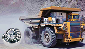
Industrial machinery and heavy-duty equipment
The characteristics of a specific system determine a wide range of factors from industrial heavy-duty equipment to industrial machines. For example, compressors and conveyors tend to employ solid shafts due to their high durability and great level of torque. Hollow shafts do not possess as great levels of torque or durability, which limits their use in certain industrial applications. However, because they are energy efficient, they are preferred in certain uses.
- Load Capacity: It is best to use solid shafts in heavy-duty machinery that require a lot of force because of demonstrate maximum loads of over 10,000 N.
- Corrosion Resistance: In equipment that is used in harsh environments, high corrosion-rated stainless steel shafts as defined in ASTM A276 standards are ideal.
- Weight-to-Strength ratio: For Hollow shafts, there is improving system efficiency without overloading it with operational stresses.
- Torsional Stiffness: The ability of a machine to endure shaft twisting under torque is known as torsional stiffness. Solid shafts possessa great deal of precision during heavy operations.
Taking into account all of this, I guarantee that my choice of motor shaft type could facilitate reliability and efficiency while bespoken to the specific features of the machinery for extended periods.
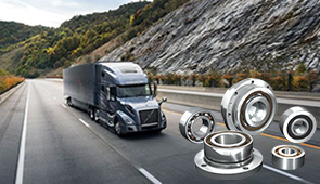
Automotive applications: From crankshafts to camshafts
Crankshafts and camshafts are crucial parts of automotive engines as they serve separate but connected functions. The motion of the pistons is reciprocating in nature, which is turned into a rotational motion by the crankshafts so that the wheels of the vehicle can be rotated. The motion of the intake and exhaust valves is timing controlled by the camshafts.
- Material Composition: The alloy steel forge methods such as AISI 4140’s preferred because of their high strength, fatigue resistance, and the ability to endure high levels of mechanical strain. Camshafts are made to endure cyclic loads by stable chilled cast iron or billet steel.
- Balance and Dynamics: Crankshafts must be balanced optimally to reduce vibrations and endure stress during high rotational speeds. Extreme precision during machining and the use of counterweights guarantee minimal concentration of stress.
- Surface Hardness: Worn surfaces can be hardened and treated with crankshafts and camshafts through the use of nitriding.
- Torsional Strength: When camshafts rotate, they should always maintain their torque and strength. This guarantees that even with large stress, the timing of the valves will remain accurate in all conditions. The torsional strength of crankshafts is also important to reduce any large torque bush forces during the operations of the engine.
- Dimensional Precision: High levels of accuracy are required during the production of both elements which will ensure tolerance in regards to engine function and reliability of its mechanics.
With these technical considerations in mind, I firmly believe that addressing such factors ensures high-functioning, reliable automotive systems that can endure prolonged operational demands while minimizing failure risks.
Specialized shafts for high-precision instruments
For instruments operating at high levels of precision, specialized shafts are a requirement, and they must meet specified technical characteristics for accuracy, longevity, and operability. These shafts frequently run under sensitive and intense environments, for example, in medical devices, aerospace, or scientific measuring instruments, where even the slightest deviation from the norm would render an incompatibility in functionality.
- Selection of the Material: Components having high tolerances need stainless steel, titanium, or other specific alloys as precision shafts usually have low thermal and dimensional stability. These materials resist wear and thermal expansion, which gives longevity and accuracy over time.
- Surface Treatment: A superior surface finish is non-negotiable for precision shafts, for it serves to reduce the wear and friction during the operation of the component. Surface roughness values that are specified are generally under 0.2 µm Ra, which is suitable for the desired performance.
- Dimensional Accuracy: The tolerances provided for the shaft’s dimension values are generally under 0.001 mm, so the performance range of the component meets the level of precision favorable for precision engineering applications.
- Dynamic Balancing: Many precise instruments depend on shafts running at high speed. In that case, dynamic balancing is employed to help reduce vibration, and hence, improve the operational stability of the instrumentation system.
- Protection from Corrosion: Shafts operating in an environment with the presence of moisture, chemicals, and other corrosive factors require high oxidation resistance, and that can be achieved through coating and advanced material treatments.
These precise measures guarantee that specific shafts will be dependable within the limits of their intended design applications.
How can custom motor shafts enhance machine functionality?
Tailoring shaft designs for unique applications
My attention is primarily on crafting solutions that fit specific custom applications when building motor shafts, and I always strive to meet the operational needs specific to the machine.
- Material Selection: The selection of the material should consider the mechanical properties required, including tensile strength, hardness, fatigue resistance, and more.
- Dimensional Precision: Application dictates the manufacturing tolerances, which in some cases can be as small as ±0.001 mm for high precision systems. This accuracy guarantees proper fitment with no chance of excessive wear and tear.
- Dynamic Load Analysis: For functions that necessitate high speeds of rotation, I evenly distribute the required shaft weight throughout its length to ensure dynamic stability and balance, which remarkably reduces vibrations when under load.
- Surface Treatments: I make use of protective surface treatments like anodizing and coating the shaft with a rust-resistant layer, or even the incorporation of corrosion-resistant coatings to further enhance the durability and resistance of the shaft to be exposed under harsh environments when required.
- Custom Features: Application needs can be addressed by incorporating various design features such as splines, keyways, threaded ends, and even hollow shafts.
By focusing on the listed aspects outlined above, I can guarantee the ultimate independent functioning of the motor shafts and components of the machine, as well as achieving outstanding performance and even suppressing the operational limits of the machine.
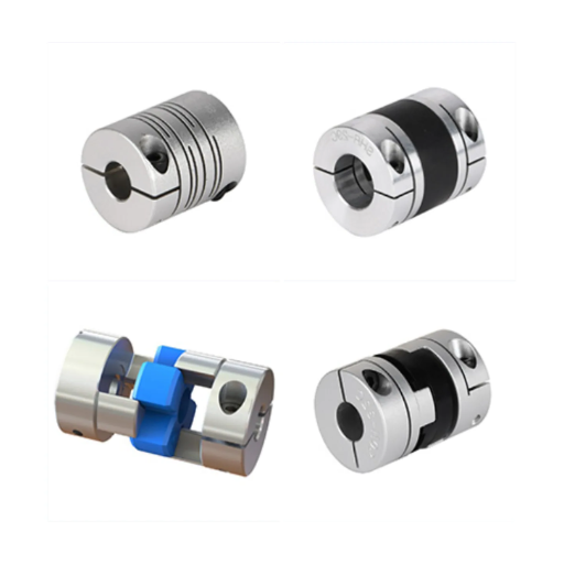
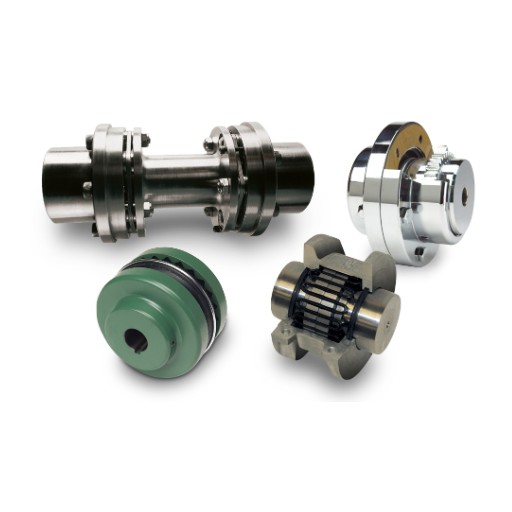
Integrating gears and couplings with custom shafts
The integration of gears and couplings with proprietary shafts requires ease of adjustment and compatibility as the most important considerations. I make certain that the shaft features like diameter, length, as well as tolerances are crafted as per the requirements of the mating components. For instance:
- Keyway Dimensions: If keyways need to be incorporated, I encoder their width and depth to conform with the requirements of various trade practices like ASME B17.1, IS0, etc. The keyway shafts will require sufficient depth and width to overcome slippage on keyways geat that excellent torque transmission is needed.
- Shaft-to-Gear Fit: I also pay attention to the interference or clearance fit. The tolerances are calculated from the properties of the shaft material and the gear material. In the case of press-fit connections, I H7/m6 and similar suffices where load conditions require it.
- Coupling Specifications: I make sure the geometry of the shaft end fits into the coupling such as appropriate spline profiles which like others conform to DIN or ANIS standards. allowances are set both for angular and parallel misalignments to lower the strain on the system.
- Material Hardness: The shaft material is selected or processed such that it mates with the running gears or coupling in terms of hardness so that adequate resistance against further wear is fulfilled like carburizing the surface to harden 58-62 HRC for challenging applications.
- Evaluation of ‘Dynamics’: The primary focus is on the load capacity, the rotational speed, and the levels of vibration. If needed, I conduct finite element analysis (FEA) by reproducing operational stresses to show the reliability of the integrated system under static and dynamic conditions.
By solving these technical problems sequentially, I guarantee that the custom shafts interface perfectly with the gears and the couplings without compromising performance, reliability, and durability. This method is critical, to the extent, that it allows for increased efficiency of sophisticated mechanized systems.
Overcoming space constraints with innovative shaft solutions
Space limitations regarding cross-section dimensions and increased operational loads put forth an assortment of challenges. To address these challenges, meticulous engineering and optimization must take place. To begin with, shafts that are placed within confined spaces must utilize high-yield alloy steels for the given shaft which help balance the performance with the given physical volume. For some, this key measurement may seem counterintuitive; however, with the use of high-strength materials, robust shafts can be developed that bear operational loads whilst possessing low cross-section measures.
Moreover, shafts themselves can be low in cross-section but allow for space optimization by utilizing hollow cores in multi-functional applications. The addition of advanced structural integrity analysis tools alongside breakthrough techniques such as additive manufacturing permits complex geometries to be implemented and at the same time, lowers the required material. Each stage of the design uses computational stress analysis to ensure shaft structures possess the needed performance without compromising on dimensions.
The use of these strategies enables a vast range of industries to effectively integrate mechanical assemblies with ease regardless of the pose of dimensional and spatial constraints. Doing so ensures longevity, durability, and above all, functional output from the shafts themselves. The aerospace and robotics industries as well as many more will benefit greatly from such innovative engineering.
Frequently Asked Questions (FAQs)
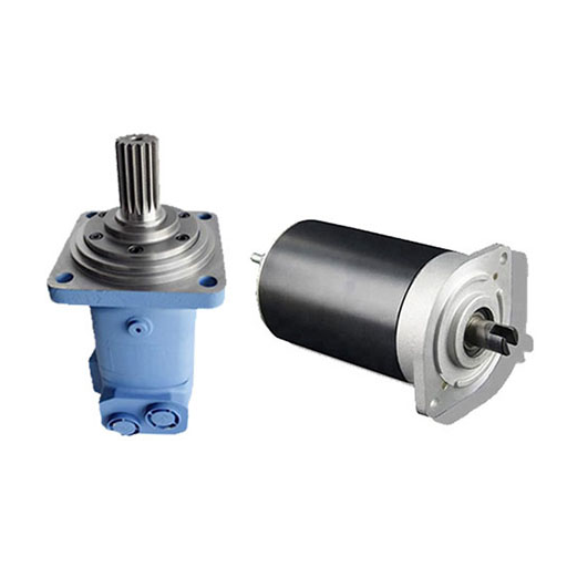
Q: What is an electric motor shaft and what is its primary function?
A: An electric motor shaft is a crucial mechanical component that is used to transmit power from the motor’s rotating parts to other mechanical components. It serves as the main output shaft, connecting the motor’s internal components to external devices or machinery. The primary function of the shaft is to transfer rotational energy and torque generated by the electric motor to the intended application or load.
Q: What are the common types of electric motor shafts?
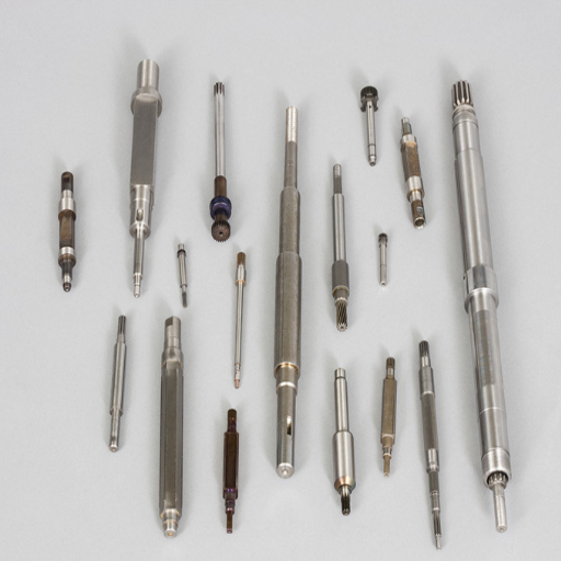
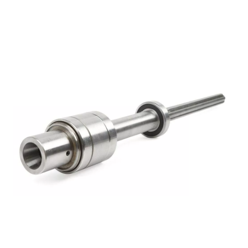
A: Common types of electric motor shafts include cylindrical shafts, which are the most basic and widely used, and stepped shafts, which have different diameters along their length. Other types include splined shafts, which have grooves for better power transmission, and hollow shafts, which are lighter and can accommodate internal components. The choice of shaft type depends on the specific application and requirements of the electric motor.
Q: What materials are commonly used for electric motor shafts?
A: The best material for electric motor shafts depends on the application, but commonly used materials include: 1. Carbon steel (e.g., 1045 steel) for general-purpose applications 2. Stainless steel for corrosion resistance 3. Alloy steels such as nickel-chromium or chromium-vanadium for high-strength applications 4. Aluminum for lightweight requirements 5. Titanium for specialized high-performance needs Motor manufacturers choose materials based on factors such as strength, durability, and cost-effectiveness.
Q: How are electric motor shafts manufactured?
A: Electric motor shafts are generally manufactured through a combination of processes. The primary method is the machining process, where the shaft is machined on a lathe to achieve the desired shape and dimensions. For mass production, shafts may be initially formed through a rolling process and then finished by machining. Heat treatment is often applied to improve the shaft’s mechanical properties. Some manufacturers of electric motors may use specialized techniques like grinding or polishing to achieve precise tolerances and surface finishes.
Q: What factors should be considered when designing an electric motor shaft?
A: When designing an electric motor shaft, several factors must be considered: 1. The motor’s horsepower and torque output 2. The weight of the shaft and attached components 3. Operating speed and potential vibrations 4. Environmental conditions (temperature, humidity, corrosive elements) 5. Required lifespan and maintenance schedule 6. Compatibility with connecting rods or other transmission components 7. Material properties such as strength, stiffness, and fatigue resistance 8. Manufacturing processes and associated costs
Q: How do stepped shafts differ from cylindrical shafts in electric motors?
A: Stepped shafts in electric motors have varying diameters along their length, while cylindrical shafts maintain a constant diameter. Stepped shafts are used to accommodate different components, such as bearings, gears, or pulleys, at specific locations along the shaft. They can also help in reducing the overall weight of the shaft while maintaining strength where needed. Cylindrical shafts, on the other hand, are simpler to manufacture and are often used in applications where uniform load distribution is required along the entire length of the shaft.
Q: What are the common issues that can affect electric motor shafts?
A: Common issues affecting electric motor shafts include: 1. Fatigue failure due to cyclic loading 2. Misalignment leading to increased wear and vibration 3. Bending or deflection under heavy loads 4. Corrosion in harsh environments 5. Residual stresses from manufacturing processes 6. Thermal expansion causing dimensional changes 7. Wear at bearing or seal contact points 8. Imbalance leads to vibration and reduced efficiency Regular maintenance and proper design can help mitigate these issues and extend the life of the motor shaft.

UCTH213-40J-300 with Setscrew(inch)
CNSORDERNO: Normal-duty(2)
TOGN: UCTH213-40J-300
SDI: B-R1/8
SD: 2 1/2
UCTH212-39J-300 with Setscrew(inch)
CNSORDERNO: Normal-duty(2)
TOGN: UCTH212-39J-300
SDI: B-R1/8
SD: 2 7/16
UCTH212-38J-300 with Setscrew(inch)
CNSORDERNO: Normal-duty(2)
TOGN: UCTH212-38J-300
SDI: B-R1/8
SD: 2 3/8
UCTH212-36J-300 with Setscrew(inch)
CNSORDERNO: Normal-duty(2)
TOGN: UCTH212-36J-300
SDI: B-R1/8
SD: 2 1/4
UCTH211-35J-300 with Setscrew(inch)
CNSORDERNO: Normal-duty(2)
TOGN: UCTH211-35J-300
SDI: B-R1/8
SD: 2 3/16
UCTH211-34J-300 with Setscrew(inch)
CNSORDERNO: Normal-duty(2)
TOGN: UCTH211-34J-300
SDI: B-R1/8
SD: 2 1/8